Digital Output Guide
A digital signal is either high or low (1 or 0). Digital output devices can generate a high or low signal, which drives other electronics. Read this guide for more information.

Quantity Available: 840
| Qty | Price |
|---|---|
| 10 | $85.50 |
| 25 | $76.50 |
| 50 | $67.50 |
| 100 | $63.00 |
The PhidgetInterfaceKit 8/8/8 is a general-purpose controller used to interface with digital and analog sensors.
The analog inputs are used to measure a 0-5V signal. Many different sensors (temperature, humidity, pressure, etc.) output a voltage that corresponds to this voltage range.
The digital inputs can interface with devices like push buttons, limit switches, and more. Each input includes hardware filtering to prevent false triggering caused by electrical noise.
The digital outputs can be used to drive LEDs, solid-state relays, and any other logic-level device.
The 1018 PhidgetInterfaceKit 8/8/8 has:
Each analog port can be opened as a VoltageInput or a VoltageRatioInput object, depending on what kind of sensor you're connecting to.
You can use your Control Panel to explore your Phidget's channels.
1. Open your Control Panel, and you will find the following channels:
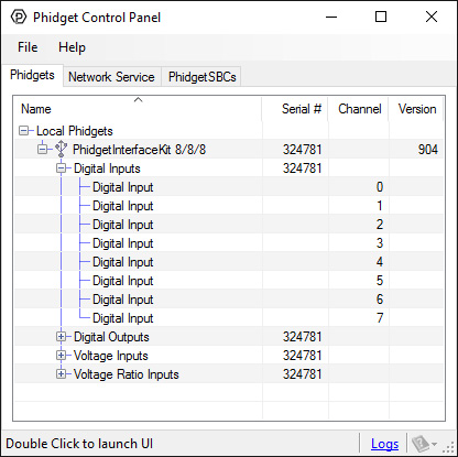
2. Double click on a channel to open an example program. Each channel belongs to the Digital Input, Digital Output, Voltage Input or Voltage Ratio Input channel class:
In your Control Panel, double click on "Digital Input":
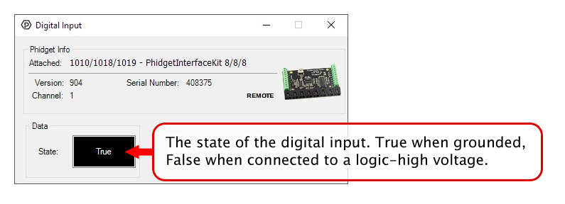
In your Control Panel, double click on "Digital Output":

In your Control Panel, double click on "Voltage Input":
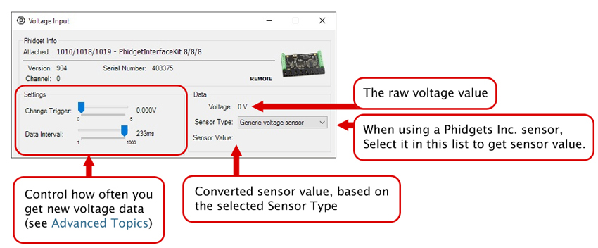
In your Control Panel, double click on "Voltage Ratio Input":
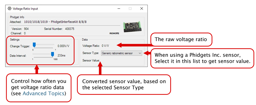
Before you open a Phidget channel in your program, you can set these properties to specify which channel to open. You can find this information through the Control Panel.
1. Open the Control Panel and double-click on the red map pin icon:

2. The Addressing Information window will open. Here you will find all the information you need to address your Phidget in your program.
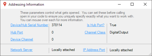
See the Phidget22 API for your language to determine exact syntax for each property.
Note: Graphing and logging is currently only supported in the Windows version of the Phidget Control Panel.
In the Phidget Control Panel, open the channel for your device and click on the ![]() icon next to the data type that you want to plot. This will open up a new window:
icon next to the data type that you want to plot. This will open up a new window:
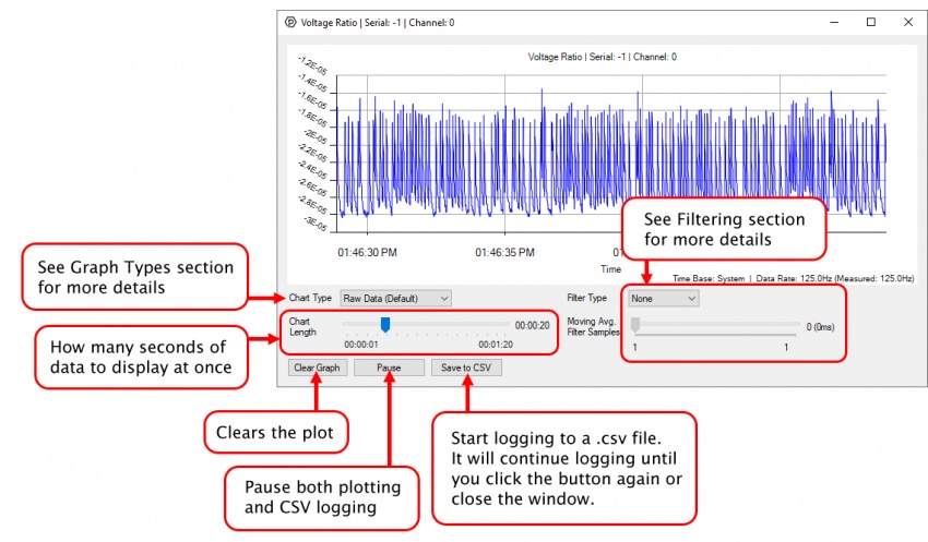
If you need more complex functionality such as logging multiple sensors to the same sheet or performing calculations on the data, you'll need to write your own program. Generally this will involve addressing the correct channel, opening it, and then creating an Event Handler and adding graphing/logging code to it.
The quickest way to get started is to download some sample code for your desired programming language and then search google for logging or plotting in that language (e.g. "how to log to csv in python") and add the code to the existing change handler.
You can perform filtering on the raw data in order to reduce noise in your graph. For more information, see the Control Panel Graphing page.
You can perform a transform on the incoming data to get different graph types that may provide insights into your sensor data. For more information on how to use these graph types, see the Control Panel Graphing page.
The Change Trigger is the minimum change in the sensor data needed to trigger a new data event.
The Data Interval is the time (in ms) between data events sent out from your Phidget.
The Data Rate is the reciprocal of Data Interval (measured in Hz), and setting it will set the reciprocal value for Data Interval and vice-versa.
You can modify one or both of these values to achieve different data outputs. You can learn more about these properties here.
Firmware Upgrade
MacOS users can upgrade device firmware by double-clicking the device row in the Phidget Control Panel.
Linux users can upgrade via the phidget22admin tool (see included readme for instructions).
Windows users can upgrade the firmware for this device using the Phidget Control Panel as shown below.
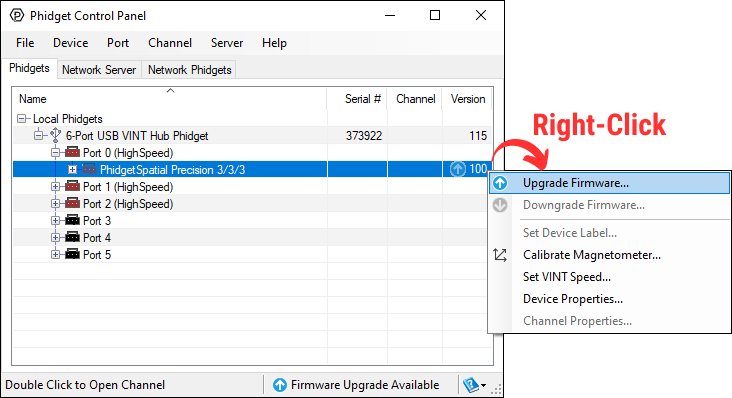
Firmware Downgrade
Firmware upgrades include important bug fixes and performance improvements, but there are some situations where you may want to revert to an old version of the firmware (for instance, when an application you're using is compiled using an older version of phidget22 that doesn't recognize the new firmware).
MacOS and Linux users can downgrade using the phidget22admin tool in the terminal (see included readme for instructions).
Windows users can downgrade directly from the Phidget Control Panel if they have driver version 1.9.20220112 or newer:
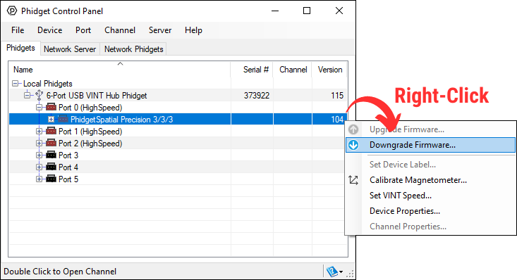
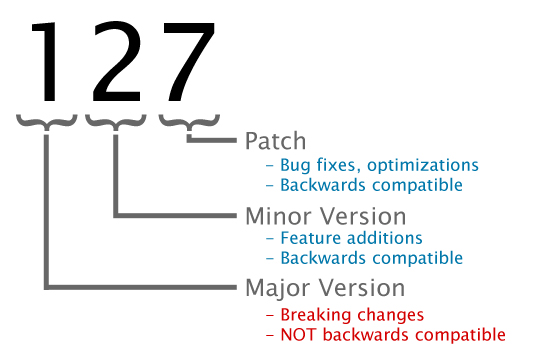
Firmware Version Numbering Schema
Phidgets device firmware is represented by a 3-digit number. For firmware patch notes, see the device history section on the Specifications tab on your device's product page.
If you want to know more about the capabilities of the analog inputs on this device, check the Analog Input Guide.
If you want to know more about the capabilities of the digital inputs on this device, check the Digital Input Guide.
If you want to know more about the capabilities of the digital outputs on this device, check the InterfaceKit Digital Outputs.
| Board Properties | |
|---|---|
| Controlled By | USB (Mini-USB) |
| USB Stack | HID |
| Driver Support | Phidget21, Phidget22 |
| API Object Name | DigitalInput, DigitalOutput, VoltageInput, VoltageRatioInput |
| USB Voltage Min | 4.6 V DC |
| USB Voltage Max | 5.5 V DC |
| Current Consumption Min | 13 mA |
| Current Consumption Max | 500 mA |
| Available External Current | 487 mA |
| Recommended Wire Size | 16 - 26 AWG |
| USB Speed | Full Speed |
| Operating Temperature Min | 0 °C |
| Operating Temperature Max | 70 °C |
| Voltage Inputs | |
| Number of Voltage Inputs | 8 |
| Voltage Input Resolution (bits) | 10 bit |
| Input Impedance | 900 kΩ |
| Input Voltage Min (DC) | 0 V DC |
| Input Voltage Max (DC) | 5 V DC |
| 5V Reference Error Max | 0.5 % |
| Voltage Input Update Rate Min | 1 samples/s |
| Voltage Input Update Rate Max (4 Channels) | 1000 samples/s |
| Voltage Input Update Rate Max (8 Channels) | 500 samples/s |
| Digital Inputs | |
| Number of Digital Inputs | 8 |
| Digital Input Type | Active Low |
| Pull-up Resistance | 15 kΩ |
| Low Voltage Max (True) | 900 mV DC |
| High Voltage Min (False) | 4.2 V DC |
| Low Voltage Trigger Length Min | 4 ms |
| High Voltage Trigger Length Min | 15 ms |
| Digital Input Voltage Max | ± 15 V DC |
| Digital Input Update Rate | 125 samples/s |
| Digital Outputs | |
| Number of Digital Outputs | 8 |
| Series Resistance | 300 Ω |
| Digital Output Available Current | 16 mA |
| Digital Output Voltage Min | 0 V DC |
| Digital Output Voltage Max | 5 V DC |
| Customs Information | |
| Canadian HS Export Code | 8471.80.00 |
| American HTS Import Code | 8471.80.40.00 |
| Country of Origin | CN (China) |
| Date | Board Revision | Device Version | Packaging Revision | Comment |
|---|---|---|---|---|
| July 2007 | 0 | 824 | Product Release | |
| September 2007 | 0 | 825 | SPI Overclocking issue fixed | |
| May 2008 | 1 | 826 | Added RC Filtering to Digital Inputs, PCB X Dimension increased to 3.27” | |
| April 2010 | 2 | 900 | Configurable data sampling speed. Replace USB connector with Mini-USB connector | |
| April 2010 | 2 | 901 | Fixed bugs relating to changing the ratiometric setting and overflow reporting | |
| September 2010 | 2 | 902 | Fixed certain output set commands from PC being ignored | |
| November 2010 | 2 | 903 | USB Product Name descriptor changed from "Phidget" to "PhidgetInterfaceKit" | |
| May 2011 | 2 | 904 | getLabelString fixed for labels longer than 7 characters | |
| November 2017 | 2 | 904 | B | Removed USB cable, added plastic shell enclosure |
| Channel Name | API | Channel |
|---|---|---|
| Voltage Input | VoltageInput | 0 - 7 |
| Voltage Ratio Input | VoltageRatioInput | 0 - 7 |
| Digital Input | DigitalInput | 0 - 7 |
| Digital Output | DigitalOutput | 0 - 7 |
| API | Detail | Language | OS | |
|---|---|---|---|---|
| VoltageInput | Visual Studio GUI | C# | Windows | Download |
| VoltageInput | Objective-C | macOS | Download | |
| VoltageInput | Swift | macOS | Download | |
| VoltageInput | Swift | iOS | Download | |
| VoltageInput | Visual Basic | Windows | Download | |
| VoltageInput | Max | Multiple | Download | |
| VoltageRatioInput | Visual Studio GUI | C# | Windows | Download |
| VoltageRatioInput | Load Cell Calibrator | C# | Windows | Download |
| VoltageRatioInput | Objective-C | macOS | Download | |
| VoltageRatioInput | Swift | macOS | Download | |
| VoltageRatioInput | Swift | iOS | Download | |
| VoltageRatioInput | Visual Basic | Windows | Download | |
| VoltageRatioInput | Max | Multiple | Download | |
| DigitalInput | Visual Studio GUI | C# | Windows | Download |
| DigitalInput | Objective-C | macOS | Download | |
| DigitalInput | Swift | macOS | Download | |
| DigitalInput | Swift | iOS | Download | |
| DigitalInput | Visual Basic | Windows | Download | |
| DigitalInput | Max | Multiple | Download | |
| DigitalOutput | Visual Studio GUI | C# | Windows | Download |
| DigitalOutput | Objective-C | macOS | Download | |
| DigitalOutput | Swift | macOS | Download | |
| DigitalOutput | Swift | iOS | Download | |
| DigitalOutput | Visual Basic | Windows | Download | |
| DigitalOutput | Max | Multiple | Download |
Use a USB cable to connect this Phidget to your computer. We have a number of different lengths available, although the maximum length of a USB cable is 5 meters due to limitations in the timing protocol. For longer distances, we recommend that you use a Single Board Computer to control the Phidget remotely.
| Product | Physical Properties | |||
|---|---|---|---|---|
| Part Number | Price | Connector A | Connector B | Cable Length |
 USB-A to Mini-B Cable 28cm 24AWG
|
$3.00 | USB Type A | USB Mini-B | 280 mm |
 USB-A to Mini-B Cable 28cm Right Angle
|
$3.50 | USB Type A | USB Mini-B (90 degree) | 280 mm |
 USB-A to Mini-B Cable 60cm 24AWG
|
$3.50 | USB Type A | USB Mini-B | 600 mm |
 USB-A to Mini-B Cable 83cm Right Angle
|
$4.50 | USB Type A | USB Mini-B (90 degree) | 830 mm |
 USB-A to Mini-B Cable 120cm 24AWG
|
$4.00 | USB Type A | USB Mini-B | 1.2 m |
 USB-A to Mini-B Cable 180cm 24AWG
|
$4.00 | USB Type A | USB Mini-B | 1.8 m |
 USB-A to Mini-B Cable 450cm, 20 AWG 2C
|
$12.00 | USB Type A | USB Mini-B | 4.5 m |
 USB-C to Mini-B Cable 60cm 24AWG
|
$5.00 | USB Type C | USB Mini-B | 600 mm |
 USB-C to Mini-B Cable 180cm 24AWG
|
$6.00 | USB Type C | USB Mini-B | 1.8 m |
To connect analog sensors you'll need Phidget cables. You can solder multiple cables together in order to make even longer Phidget cables, but you should be aware of the effects of having long wires in your system.
| Product | Physical Properties | |
|---|---|---|
| Part Number | Price | Cable Length |
 Phidget Cable 10cm
|
$1.50 | 100 mm |
 Phidget Cable 30cm
|
$1.75 | 300 mm |
 Phidget Cable 60cm
|
$2.00 | 600 mm |
 Phidget Cable 60cm
|
$2.00 | 600 mm |
 Phidget Cable 90cm
|
$2.00 | 900 mm |
 Phidget Cable 120cm
|
$2.25 | 1.2 m |
 Phidget Cable 150cm
|
$2.50 | 1.5 m |
 Phidget Cable 180cm
|
$2.75 | 1.8 m |
 Phidget Cable 350cm
|
$3.00 | 3.5 m |
 Phidget Cable Kit
|
$10.00 | 80 mm |
 Phidget Cable Extension Wire 22AWG
|
$0.75/Meter | — |
The following boards also have analog inputs, digital inputs, and digital outputs:
| Product | Voltage Inputs | Digital Outputs | Digital Inputs | |
|---|---|---|---|---|
| Part Number | Price | Number of Voltage Inputs | Number of Digital Outputs | Number of Digital Inputs |
 PhidgetInterfaceKit 8/8/8
|
$90.00 | 8 | 8 | 8 |
 PhidgetInterfaceKit 2/2/2
|
$50.00 | 2 | 2 | 2 |
 PhidgetInterfaceKit 8/8/8
|
$90.00 | 8 | 8 | 8 |
 PhidgetInterfaceKit 8/8/8 Mini-Format
|
$70.00 | 8 | 8 | 8 |
 PhidgetInterfaceKit 8/8/8 w/6 Port Hub
|
$110.00 | 8 | 8 | 8 |
 PhidgetTextLCD 20X2 : White : Integrated PhidgetInterfaceKit 8/8/8
|
$70.00 | 8 | 8 | 8 |
These devices have VINT ports, which can each be configured to behave as an analog input, digital input, or digital output:
| Product | Board Properties | |||
|---|---|---|---|---|
| Part Number | Price | Number of VINT Ports | VINT Communication Speed Max | Controlled By |
 VINT Hub Phidget
|
$40.00 | 6 | 1 Mbit/s | USB (Mini-USB) |
 1-Port VINT Hub Phidget
|
$26.00 | 1 | 1 Mbit/s | USB (USB-A) |
 VINT Hub Phidget
|
$35.00 | 6 | 1 Mbit/s | USB (Mini-USB) |
 Wireless VINT Hub
|
$65.00 | 6 | 100 kbit/s | Local Network (Ethernet or Wi-Fi) |
 PhidgetSBC4
|
$130.00 | 6 | 100 kbit/s | — |
Contact us for other compliance-related inquires.