Data Interval/Change Trigger
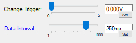
Phidget devices often send streams of sensor and state data to attached channels. The rate at which that data is delivered can be controlled by setting the DataInterval property of a channel. A threshold can be set to filter data that does not vary by more than a defined amount by setting the ChangeTrigger property of a channel.
Phidget device channels are initialized with a default DataInterval specific to the device and a ChangeTrigger of zero when they are attached. See the Phidget22 API for more information.
In most cases, it is likely that you'll simply use these properties as follows:
- Keep the
ChangeTriggerat zero and select theDataIntervalbased on how often you want your program to receive data. This configuration is useful in data logging applications and when data will be represented in a graph. - Or, keep the
DataIntervalat a minimal interval, and set theChangeTriggerto the lowest relevant value for the quality you are measuring. This is useful for applications were you want to ignore values below a certain threshold or are displaying sensor values to be read in real-time.
Keep reading below for more details on these properties.
Data Interval and Data Rate
Data Interval
The DataInterval property, measured in milliseconds, determines the rate at which the device channel will report data back to your program. If a channel is open in more than one program (i.e. with remote connections over the Phidget Network Server), all instances of that channel will share one data interval, and changing it in one program will change it in all others. When this change occurs, a PropertyChange event will be triggered in each of the other programs so they can adjust accordingly if needed.
The minimum, maximum and default DataInterval varies for each device. Refer to the Phidget22 API and check the MinDataInterval and MaxDataInterval properties for your device to see the limits. In most cases, you will probably want to set the DataInterval to the minimum value to get as much data as possible. However, in some applications such as long-run data logging, you may want to increase DataInterval to make the resulting data set more manageable. You may also want to increase the DataInterval if you're using a PhidgetSBC or HUB5000, since they can be overwhelmed if too many channels are running at the minimum DataInterval.
Data Rate
DataRate is the reciprocal of DataInterval: instead of being measured in milliseconds between data samples, it is measured in hertz (the number of samples provided within one second). When you set the DataInterval for your device, the DataRate will also be set to the corresponding value and vice-versa. In the Phidget Control Panel, you can click on the DataInterval in order to switch between the two. In most cases, whether you use one or the other is a matter of personal preference. However, for devices that can provide data in faster than 1ms intervals, you must use Data Rate to get the most data because DataInterval is an integer and can't go below 1 millisecond.
While the Phidgets libraries will allow you to set any value within the specified minimum and maximum for your device, sometimes hardware limitations cause certain data rates to be unavailable. In this case, the nearest possible data rate will be selected instead. For more details on this behaviour, see the Advanced Topics section below.
Change Trigger
The ChangeTrigger property of a channel enables a filter that only passes data when that data has changed by an amount greater than or equal to the ChangeTrigger. For example, if the DataInterval was set to 0.7, new data would only be delivered to the channel when that new data differed from the previously delivered data by at least 0.7.
It can be useful to set a change trigger to reduce amount of data, only receiving data change events when meaningful thresholds are reached. For example, an application that displayed temperature on an LCD may only be interested on 0.5°C changes. By setting the ChangeTrigger to 0.5, you could avoid having a fast-changing number that is difficult to read, without sacrificing response time.
Advanced Topics
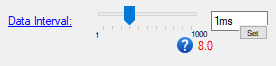
When you see a red number below the slider when you set the DataInterval or DataRate, it means that the DataInterval or DataRate has changed, and the red number is the actual speed that the channel is now set to. The number in black text in the box above it is what you previously had it set to.
There are two reasons why this can happen:
- If you have the channel open in another program over the network server (or another instance of the Control Panel), changing these properties there will cause the Control Panel Example to update to the new value.
- If you have a device that enforces restrictions on DataInterval based on how many channels are open, an you just opened another channel on the device or changed the DataInterval or DataRate on another channel, then this channel may have been adjusted to stay within the new limit.
The change is possible because a PropertyChanged event is thrown in both of these cases. If you want to use this event in your program, you can read more about it by going to the Phidget22 API and selecting the "PhidgetAPI" section for your device.
There are a couple of factors that affect the rate at which data can be sent, such as ADC limitations and communication speed limits. Because of this, you may try to set the DataRate to 300Hz, but only get data at 250Hz. Usually the device will set the next-slowest possible rate than what was requested. If you want to know for certain what rate is actually being used, you can check the DataRate property after setting it.
You can also use the Phidget Control Panel to test this behaviour on your devices. When you click on the graph button beside your data readout, you can see the real data rate on the bottom of the graph:
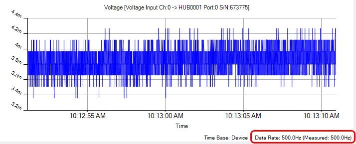
The first number is the result of getting the DataRate value from the API, and the second number is the result of a manual time calculation of the data coming in (if the numbers don't match, it could indicate latency issues or a bug in the device firmware).
In some complex situations, you may want to set both the ChangeTrigger and the DataInterval to non-trivial values. This will result in expected behavior: The channel will check at the DataInterval whether or not the new data differs from the last delivered data by an amount greater than or equal to the ChangeTrigger. If the data passes the change trigger filter, that data will be delivered, if the data does not, the channel will wait until the next data interval and check again.
The only complication is when you consider a situation where the value has spiked by a large amount and then returned to the baseline, in-between intervals. For example, suppose you have a voltage sensor and you've set the DataInterval to 5 milliseconds an the VoltageChangeTrigger to 3mV. The way this is handled depends on whether you're using a USB Phidget or a VINT Phidget:
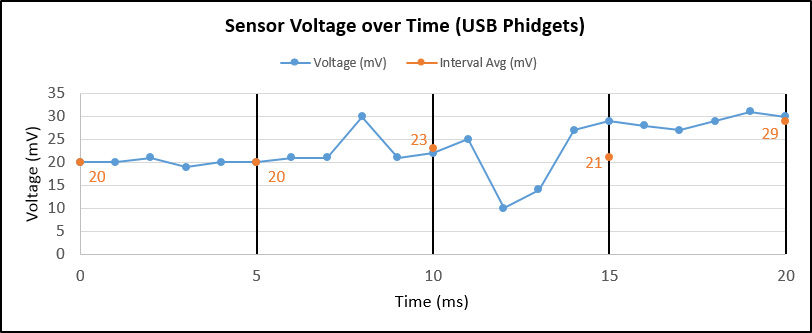
In this example, the blue data points represent the real value of the voltage at any given time. The thick black bars represent the sampling interval, which is 5 milliseconds. When a USB Phidget samples at a slower rate than its default, it will average the last interval worth of samples together and report that value on each interval. This average is represented by the orange data point that lands on each interval line. It is this average that is compared against the change trigger to decide whether or not a data event fires or not. Let's step through each interval:
Interval 1 (0-5ms): The voltage stays mostly stable throughout this interval. The average at the end of the interval is 20mV, which is no different than our first sample. Since our change trigger is 3mV, an event does not fire at the 5ms mark.
Interval 2 (5-10ms): In this interval, the voltage spikes to 30mV and then drops back down. The average for this interval is 23mV, which is 3mV higher than our last event at 0ms. Thus, the change is sufficient to cause a data even to fire at 10ms.
Interval 3 (10-15ms): In this interval, the voltage drops down to 10mV and then rises close to 30mV. The average for this interval is 21mV, which is only 2mV off from our last event. Since this does not meet our change trigger, an event does not fire.
Interval 4 (15-20ms): In this interval, the voltage remains relatively stable at around 28mV. However, the average for this interval is 29mV, which is much higher than our last data event (23mV). This change of 6mV is greater than our change trigger, so an event fires.
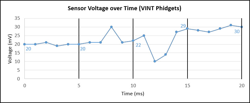
Let's see how a VINT devices behaves in the same example. Now, instead of averaging all of the values in the past interval, the VINT device goes to sleep to save power. That means it only cares about the data values on each interval line, and ignores all others.
Interval 1 (0-5ms): The device wakes up and sees a value of 20mV, which is no different than the starting value of 20mV. No event is fired.
Interval 2 (5-10ms): The device wakes up and sees 22mV, which does not differ enough from the last event of 20mV, as our change trigger is 3mV. No event is fired.
Interval 3 (10-15ms): The device wakes up and sees 29mV, which is enough of a change to fire a data event.
Interval 4 (15-20ms): The device wakes up and sees 30mV, which is only 1mV off from the last event, which is not sufficient to trigger a new event.
Further Reading
Phidget Programming Basics - Here you can find the basic concepts to help you get started with making your own programs that use Phidgets.
Polling vs. Events - Your program can gather data in either a polling-driven or event-driven manner. Learn the difference to determine which is best for your application.
Using Multiple Phidgets - Learn how to use more than one Phidget in your program. This page will guide you through the steps.
Logging, Exceptions, and Errors - Learn about all the tools you can use to debug your program.
Phidget Network Server - Phidgets can be controlled and communicated with over your network- either wirelessly or over ethernet.
Best Phidgets Practices - Good programming habits that will save you from common problems when writing code for your Phidgets.