Digital Input Guide
Introduction
Digital Inputs can be used to convey the state of various devices such as push buttons, limit switches, relays, or logic level outputs.
Digital Inputs are one of the easiest components to work with, since all that is required is a simple check to see which state they are in when an event triggers.
If you think your project could benefit from the use of digital inputs, check out this list of Phidgets with Digital Inputs
Phidget Digital Input Types
Phidgets Digital Inputs fall into one of two categories: Active Low and Active High.
Active Low digital inputs will most often be used to detect whether a switch between the input and ground has been closed. These inputs will report TRUE when the switch is closed and FALSE when the switch is open.
More generally, Active Low digital inputs consider their state to be TRUE when the voltage is closer to 0V (low), and FALSE when closer to 5V (high).
Active High digital inputs are designed to detect the presence of an external voltage-based digital signal. These inputs will report TRUE when the voltage on the input is above a given threshold (high), and FALSE when the input voltage is close to 0V (low).
See the specification table on your Phidget's product page to determine if your device has Active High or Active Low inputs and to see the exact voltage levels they switch at.
Technical Details
Logic Levels
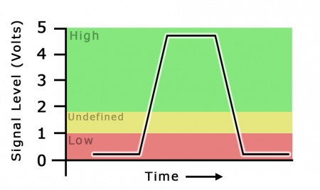
Digital Inputs have two states: Low and High. These states, called logic levels, refer to the voltage on the input being measured. If the voltage is above a given threshold, it is considered High, and if it is below a lower threshold it is considered Low.
In simple terms, with a 5V Digital Input, it is guaranteed that 5V will be High, and 0V will be Low.
For a more specific example, on the HUB0000, the minimum voltage for a guaranteed High logic level to be detected is 1.8V DC, while the highest guaranteed Low voltage is 1V. The input signal should avoid staying at any voltage between these two values, as it will produce inconsistent results. You can find these thresholds on your Phidget's product page under the headings 'High Voltage Min' and 'Low Voltage Max'.
Any signal that is expected to interact with more than just these 2 states is inappropriate for this type of input.
Ground Protection
Ground terminals on many digital inputs share a common ground with with USB ground. If your digital input is not internally isolated, these terminals will expose the USB ground potential of the PC to which they are connected. Be sure you are completely familiar with any circuit you intend to connect to the digital input before it is connected. If a reverse voltage or dangerously high voltage is applied to the input or output terminals, damage to the Phidget or the PC may result.
Unknown State
If you poll the state of the Digital Input too soon after it has attached, before the device has had a chance to send its state information, you will get an unknown state error. Be sure to check the error codes when getting the state to ensure it is valid.