Servo Motor and Controller Guide
Learn about servo motors and servo motor controllers in this guide, including: how servo motors work, how to choose a servo motor, types of servo motors, and more.


Quantity Available: 68
| Qty | Price |
|---|---|
| 10 | $33.25 |
| 25 | $29.75 |
| 50 | $26.25 |
| 100 | $24.50 |
Note: The 1066_1B is identical to the 1066_1, except that you have the option of whether you want to include the USB cable.
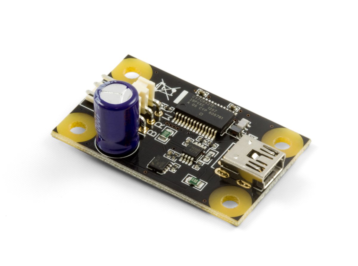
The PhidgetAdvancedServo 1-Motor allows you to control the position, velocity, and acceleration of one RC servo motor and connects directly to your computer's USB port.
It is powered solely by the USB connection – no additional power source is required and it can power servos with a rated current of up to 450mA.
The PhidgetAdvancedServo can drive one servo motor. Each of the servo motors in the list below is compatible with this Phidget and plugs directly to the board with no extra cables or soldering required. Servos come in two major varieties: limited rotation and continuous rotation. With limited rotation servos, the motor has a limited range of motion, but can be precisely controlled within that range. A continuous rotation servo can rotate continuously, but you won't be able to tell the servo to move to a specific location in degrees; instead you'll specify a direction and speed and for it to rotate at.
| Product | Motor Properties | ||||
|---|---|---|---|---|---|
| Part Number | Price | Motor Type | Range of Rotation | Rated Torque | Rated Speed |
 Hitec Continuous Rotation Servo
|
$18.75 | Continuous Rotation Servo | — | 2.8 kg·cm | 44 RPM |
 Hitec Mega Sail Servo
|
$52.00 | Limited Rotation Servo | 180° | 19.8 kg·cm | 125°/s |
 Hitec Super Torque Servo
|
$40.50 | Limited Rotation Servo | 180° | 7.7 kg·cm | 300°/s |
 Hitec Winch Servo
|
$57.75 | Limited Rotation Servo | Approx. 2700° | 11 kg·cm | 225°/s |
 SpringRC Standard Servo
|
$8.00 | Limited Rotation Servo | 180° | 3.5 kg·cm | 400°/s |
 SpringRC Small Servo
|
$10.00 | Limited Rotation Servo | 180° | 2.4 kg·cm | 375°/s |
 SpringRC High Torque Continuous Rotation Servo
|
$18.00 | Continuous Rotation Servo | — | 12.2 kg·cm | 50 RPM |
Use a USB cable to connect this Phidget to your computer. We have a number of different lengths available, although the maximum length of a USB cable is 5 meters due to limitations in the timing protocol. For longer distances, we recommend that you use a Single Board Computer to control the Phidget remotely.
| Product | Physical Properties | |||
|---|---|---|---|---|
| Part Number | Price | Connector A | Connector B | Cable Length |
 USB-A to Mini-B Cable 28cm 24AWG
|
$3.00 | USB Type A | USB Mini-B | 280 mm |
 USB-A to Mini-B Cable 28cm Right Angle
|
$3.50 | USB Type A | USB Mini-B (90 degree) | 280 mm |
 USB-A to Mini-B Cable 60cm 24AWG
|
$3.50 | USB Type A | USB Mini-B | 600 mm |
 USB-A to Mini-B Cable 83cm Right Angle
|
$4.50 | USB Type A | USB Mini-B (90 degree) | 830 mm |
 USB-A to Mini-B Cable 120cm 24AWG
|
$4.00 | USB Type A | USB Mini-B | 1.2 m |
 USB-A to Mini-B Cable 180cm 24AWG
|
$4.00 | USB Type A | USB Mini-B | 1.8 m |
 USB-A to Mini-B Cable 450cm, 20 AWG 2C
|
$12.00 | USB Type A | USB Mini-B | 4.5 m |
 USB-C to Mini-B Cable 60cm 24AWG
|
$5.00 | USB Type C | USB Mini-B | 600 mm |
 USB-C to Mini-B Cable 180cm 24AWG
|
$6.00 | USB Type C | USB Mini-B | 1.8 m |
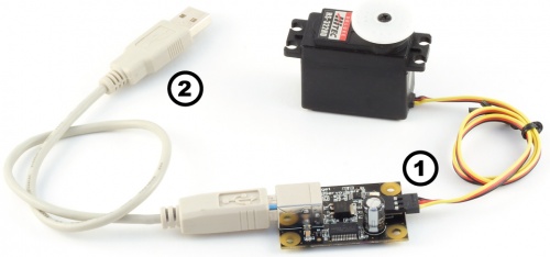
Welcome to the 1066 user guide! In order to get started, make sure you have the following hardware on hand:
Next, you will need to connect the pieces:
Now that you have everything together, let's start using the 1066!
In order to demonstrate the functionality of the 1066, the Phidget Control Panel running on a Windows machine will be used.
The Phidget Control Panel is available for use on both macOS and Windows machines.
To open the Phidget Control Panel on Windows, find the ![]() icon in the taskbar. If it is not there, open up the start menu and search for Phidget Control Panel
icon in the taskbar. If it is not there, open up the start menu and search for Phidget Control Panel
To open the Phidget Control Panel on macOS, open Finder and navigate to the Phidget Control Panel in the Applications list. Double click on the ![]() icon to bring up the Phidget Control Panel.
icon to bring up the Phidget Control Panel.
For more information, take a look at the getting started guide for your operating system:
Linux users can follow the getting started with Linux guide and continue reading here for more information about the 1066.
After plugging the 1066 into your computer and opening the Phidget Control Panel, you will see something like this:
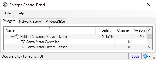
The Phidget Control Panel will list all connected Phidgets and associated objects, as well as the following information:
The Phidget Control Panel can also be used to test your device. Double-clicking on an object will open an example.
Double-click on the RCServo object, labelled RC Servo Motor Controller, in order to run the example:
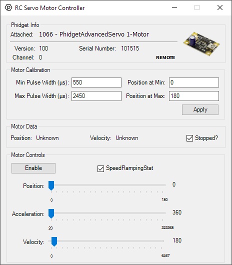
General information about the selected object will be displayed at the top of the window. You can also experiment with the following functionality:
Double-click on the Current Input object , labelled RC Servo Motor Current Sensor, in order to run the example:
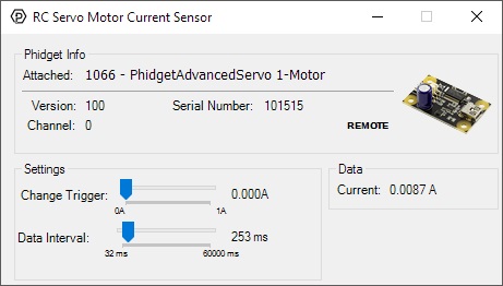
General information about the selected object will be displayed at the top of the window. You can also experiment with the following functionality:
Before you can access the device in your own code, and from our examples, you'll need to take note of the addressing parameters for your Phidget. These will indicate how the Phidget is physically connected to your application. For simplicity, these parameters can be found by clicking the button at the top of the Control Panel example for that Phidget.

In the Addressing Information window, the section above the line displays information you will need to connect to your Phidget from any application. In particular, note the Channel Class field as this will be the API you will need to use with your Phidget, and the type of example you should use to get started with it. The section below the line provides information about the network the Phidget is connected on if it is attached remotely. Keep track of these parameters moving forward, as you will need them once you start running our examples or your own code.

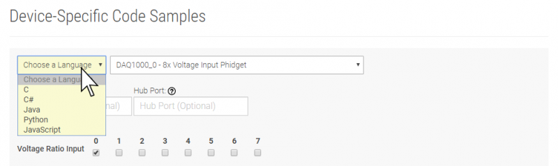
You are now ready to start writing your own code for the device. The best way to do that is to start from our Code Samples.
Select your programming language of choice from the drop-down list to get an example for your device. You can use the options provided to further customize the example to best suit your needs.
Once you have your example, you will need to follow the instructions on the page for your programming language to get it running. To find these instructions, select your programming language from the Programming Languages page.
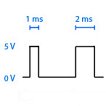
An RC servo motor can be instructed to move to a desired position by the controller. Internally, it monitors the current position, and drives the motor as fast as it can until it reaches the desired position. This is a very cheap and simple way to control a motor. It has some limitations - there is no way for the controller to know the current position and speed of the motor. Applications that want smooth movement suffer from the aggressive acceleration.
The 1066 is able to address some of these limitations. Instead of sending the desired position immediately, the 1066 sends a series of progressive positions according to acceleration and velocity parameters. In most applications, this dramatically smooths the operation of the servo, and allows reasonably precise control of position, velocity and acceleration. The 1066 has a built in switching regulator - this allows it to efficiently operate from a wide voltage range (6-15VDC), and maintain proper power to the servo motors even if the power supply is varying. This built in voltage regulator will not operate if your power supply is undersized.
For more information about servo motors and controllers, check out the Servo Motor and Controller Guide.
The easiest way to determine the range of pulse widths to use is to check your servo's datasheet or specification table and use the numbers provided. If you do not have the numbers, you can determine them by following this process:
This process is important because selecting a minimum or maximum pulse width that results in the motor stalling could have an impact on the motor's lifespan if it spends a lot of time holding position at those locations.
If you have a continuous rotation servo, you don't have to worry about it stalling so you can just increase the maximum and decrease the minimum until you reach the servo's maximum speed.
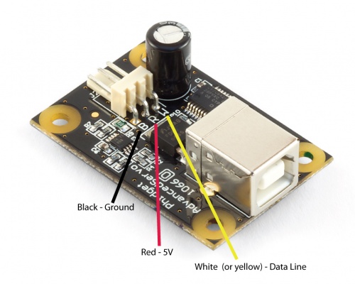
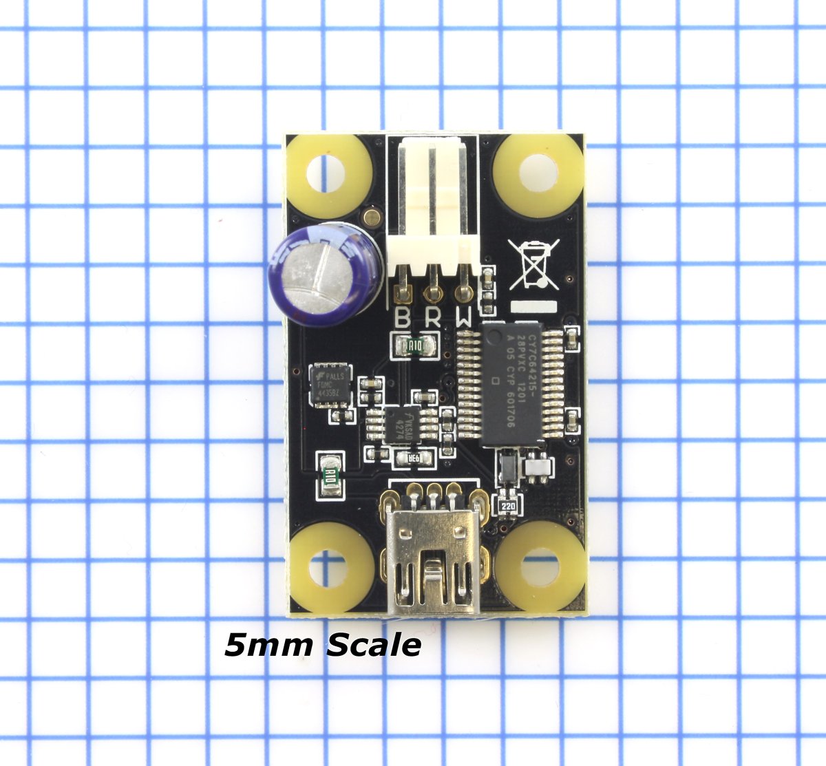
The pins on the 1066 are labelled B R W on the board:
The 1066 continuously measures the current consumed by each motor. The current roughly corresponds to torque, making it possible to detect several scenarios.
The 1066 does not know the current position of the motor on its own. If your motor is free to move, and is not being driven beyond the physical limitations of the motor, the position returned to your application will be very close to the position of the motor.
A continuous rotation servo is a servo motor that has had its headgear-stop removed and potentiometer replaced by two matched-value resistors. This has the effect of allowing the motor to rotate freely through a full range of motion, but disables the motor’s ability to control it’s position.
When using the 1066 with a servo motor modified in this way, the position control in software becomes the motor's speed control. Because the two resistors that replace the motor’s potentiometer are matched in value, the motor will always think its shaft is at center position. If the target position in software is set to center, the motor will believe it has achieved the target and will therefore not rotate. The further away from center the target position is set to, the faster the motor will rotate (trying to reach that position, but never doing so). Changing the value above or below center changes the direction of rotation.
Electronic Speed Controllers are commonly used in RC hobby planes, cars, helicopters. It's a controller that accepts a PWM input signal, and controls a motor based on that signal. The ESC accepts power from an external source, normally a battery pack.
ESCs can be controlled by the 1066, but the vast majority of ESCs on the market will destroy the 1066 if they are plugged in without modification. In a hobby RC system, the ESC is responsible for regulating some of the battery current down to ~5V, and supplying it to the radio receiver. An ESC designed to the power the receiver will advertise that it has a Battery Eliminator Circuit (BEC). When you plug an ESC into the 1066, the 1066 is acting as the radio receiver. The 1066 was not designed to be powered by the devices it controls, and the voltage regulator on the 1066 will self-destruct if a device tries to power it. If the center pin from the 3-wire servo connector between the 1066 and the ESC is disconnected, the BEC on the ESC will not be able to power the 1066, and the voltage regulator will not fail.
How the ESC inteprets the PWM signal and controls the motor is a function of the ESC. Higher end ESCs can be configured based on the application.
The hobby RC market has transitioned to Brushless DC Motors (BLDC). As you select an ESC, watch that the battery voltage input matches that of your system, and the type of motor controlled is what you have. Brushed DC and Brushless DC Motors are completely different, and require different controllers.
Wiring layout is critical with ESCs. The currents to the motor and on the ground return can be enormous. If these currents end up travelling back through USB cables, the system will not be stable. Some ESCs are optically isolated (OPTO) - a big advantage that reduces interference.
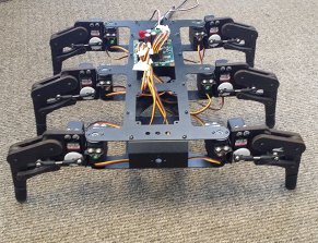
Many applications call for several servo motors operating in unison - for example, operating a CNC table, or a robot arm. Highly precise synchronization of servos using the 1066 is not possible, as the sequencing will be affected by the real-time performance of your operating system. Each servo is controlled as a independent unit, so there is no way of arranging for a particular action to happen to all motors at the same time. Typical jitter can be 10-30mS.
You can still use the 1066 to power servos that are rated for a higher power, but you will need to provide an external power supply. Cut and reattach the red and black wires as shown in the diagram below.
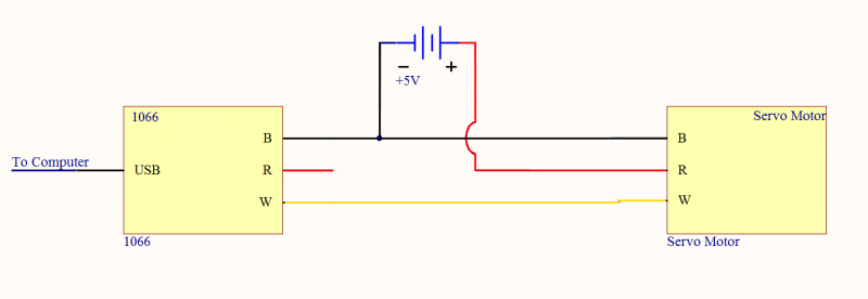
Make sure you disconnect the red wire from the 1066 as pictured, because reverse current from the external power supply could damage the servo controller board.
| Servo Controller | |
|---|---|
| API Object Name | AdvancedServo |
| Number of Motor Ports | 1 |
| Pulse Width Min | 83.3 ns |
| Pulse Width Max | 2.7 ms |
| Pulse Width Resolution | 83.3 ns |
| Pulse Code Period Max | 25 ms |
| Measurement Current Min | 30 mA |
| Measurement Current Max | 500 mA |
| Measurement Current Error | 10 % |
| Board Properties | |
| Controlled By | USB (Mini-USB) |
| USB Stack | HID |
| Driver Support | Phidget21, Phidget22 |
| API Object Name | RCServo |
| Electrical Properties | |
| Current Consumption Min | 30 mA |
| Current Consumption Max | 500 mA |
| USB Voltage Min | 4.8 V DC |
| USB Voltage Max | 5.3 V DC |
| Continuous Motor Current Max | 450 mA |
| Output Impedance (Motor) | 200 Ω |
| USB Speed | Full Speed |
| Physical Properties | |
| Object Temperature Min | 0 °C |
| Object Temperature Max | 70 °C |
| Customs Information | |
| Canadian HS Export Code | 8471.80.00 |
| American HTS Import Code | 8471.80.40.00 |
| Country of Origin | CN (China) |
| Date | Board Revision | Device Version | Packaging Revision | Comment |
|---|---|---|---|---|
| July 2009 | 0 | 100 | Product Release | |
| May 2011 | 0 | 101 | getLabelString fix for labels > 7 characters | |
| October 2012 | 1 | 101 | Mini USB Connector, Layout Change | |
| January 2018 | 1 | 101 | B | Removed USB cable from packaging |
| Channel Name | API | Channel |
|---|---|---|
| RC Servo Motor Controller | RCServo | 0 |
| RC Servo Motor Current Sensor | CurrentInput | 0 |
Each servo motor behaves slightly differently. The Phidgets API provides calibration parameters for a number of different models of servo motors; however these values are generic with respect to the model and not specific to each individual unit. It is possible to generate your own values through some manual calibration in the event that your application requires very accurate control or if you are using a servo for which default values are not provided. Read the following manual to find out how to do it.
| API | Detail | Language | OS | |
|---|---|---|---|---|
| RCServo | Visual Studio GUI | C# | Windows | Download |
| RCServo | Objective-C | macOS | Download | |
| RCServo | Swift | macOS | Download | |
| RCServo | Swift | iOS | Download | |
| RCServo | Visual Basic | Windows | Download | |
| RCServo | Max | Multiple | Download | |
| CurrentInput | Visual Studio GUI | C# | Windows | Download |
| CurrentInput | Objective-C | macOS | Download | |
| CurrentInput | Swift | macOS | Download | |
| CurrentInput | Swift | iOS | Download | |
| CurrentInput | Visual Basic | Windows | Download | |
| CurrentInput | Max | Multiple | Download |