Digital Output Guide
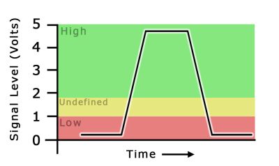
A digital signal is either high or low (1 or 0). Digital output devices can generate a high or low signal, which drives other electronics. Read this guide for more information.
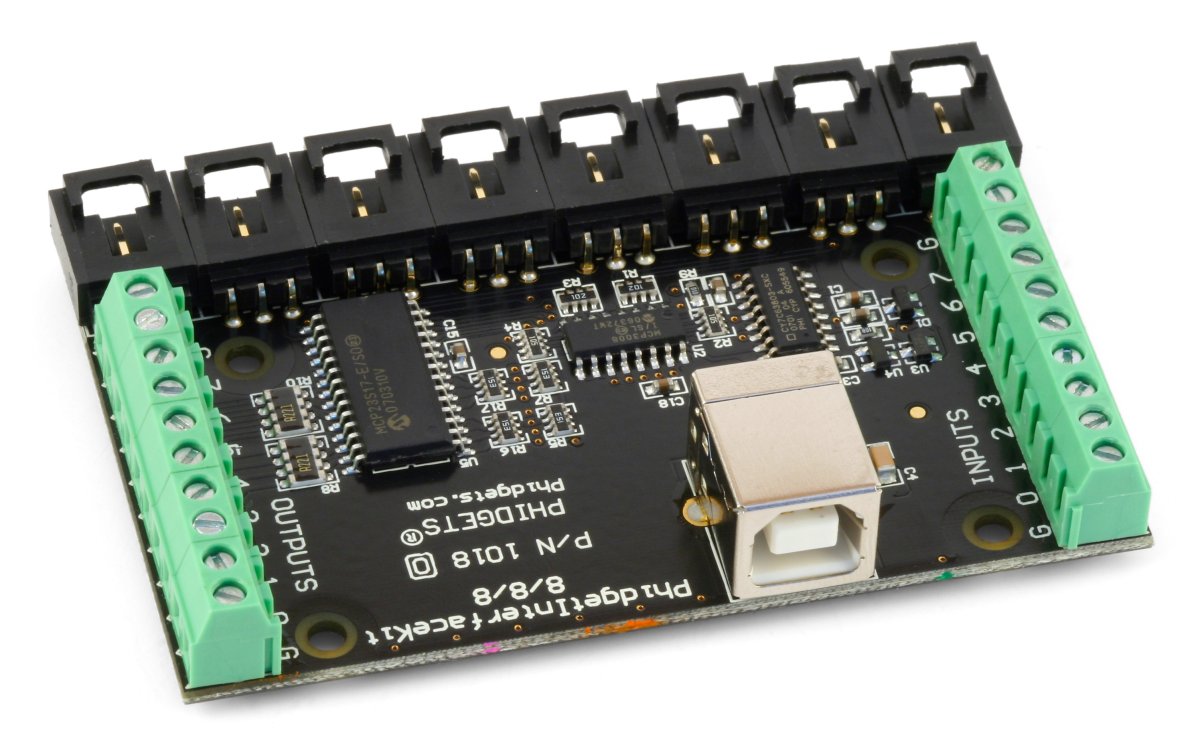
Replaced by the 1018 - PhidgetInterfaceKit 8/8/8.
The Analog Inputs are used to measure continuous quantities, such as temperature, humidity, position, or pressure. Phidgets offers a wide variety of sensors that can be plugged directly into the board using the cable included with the sensor.
The Digital Inputs can be used to convey the state of devices such as push buttons, limit switches, relays, and logic levels.
The Digital Outputs can be used to drive LEDs, solid state relays (such as the 3052 SSR Relay Board), transistors; in fact, anything that will accept a CMOS signal.
Comes packaged with a 180cm USB Cable, a Getting Started Manual, a mounting hardware kit, and a sheet of labels.
| Customs Information | |
|---|---|
| Canadian HS Export Code | 8471.80.00 |
| American HTS Import Code | 8471.80.40.00 |
| Country of Origin | CN (China) |
| Device | Object Name | Channel |
|---|---|---|
| Voltage Inputs | VoltageInput | 0 - 7 |
| Ratiometric Voltage Inputs | VoltageRatioInput | 0 - 7 |
| Digital Inputs | DigitalInput | 0 - 7 |
| Digital Outputs | DigitalOutput | 0 - 7 |
| API | Detail | Language | OS | |
|---|---|---|---|---|
| VoltageInput | Visual Studio GUI | C# | Windows | Download |
| VoltageInput | Objective-C | macOS | Download | |
| VoltageInput | Swift | macOS | Download | |
| VoltageInput | Swift | iOS | Download | |
| VoltageInput | Visual Basic | Windows | Download | |
| VoltageInput | Max | Multiple | Download | |
| VoltageRatioInput | Visual Studio GUI | C# | Windows | Download |
| VoltageRatioInput | Load Cell Calibrator | C# | Windows | Download |
| VoltageRatioInput | Objective-C | macOS | Download | |
| VoltageRatioInput | Swift | macOS | Download | |
| VoltageRatioInput | Swift | iOS | Download | |
| VoltageRatioInput | Visual Basic | Windows | Download | |
| VoltageRatioInput | Max | Multiple | Download | |
| DigitalInput | Visual Studio GUI | C# | Windows | Download |
| DigitalInput | Objective-C | macOS | Download | |
| DigitalInput | Swift | macOS | Download | |
| DigitalInput | Swift | iOS | Download | |
| DigitalInput | Visual Basic | Windows | Download | |
| DigitalInput | Max | Multiple | Download | |
| DigitalOutput | Visual Studio GUI | C# | Windows | Download |
| DigitalOutput | Objective-C | macOS | Download | |
| DigitalOutput | Swift | macOS | Download | |
| DigitalOutput | Swift | iOS | Download | |
| DigitalOutput | Visual Basic | Windows | Download | |
| DigitalOutput | Max | Multiple | Download |
| Date | Board Revision | Device Version | Comment |
|---|---|---|---|
| July 2007 | 0 | 824 | Product Release |
| September 2007 | 0 | 825 | SPI Overclocking issue fixed |
| Ma 2008 | Product replaced by 1018_1. | ||
The 1018 PhidgetInterfaceKit 8/8/8 has:
Each analog port can be opened as a VoltageInput or a VoltageRatioInput object, depending on what kind of sensor you're connecting to.
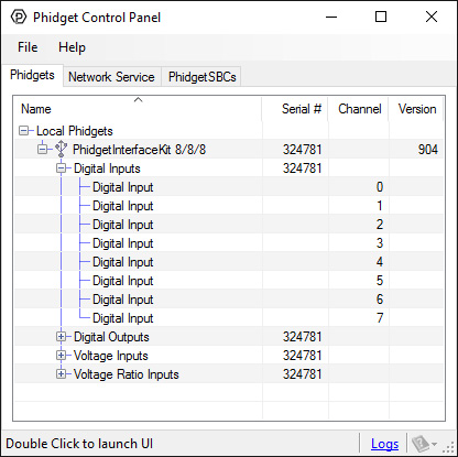
You can use your Control Panel to explore your Phidget's channels.
1. Open your Control Panel, and you will find the following channels:
2. Double click on a channel to open an example program. Each channel belongs to the Digital Input, Digital Output, Voltage Input or Voltage Ratio Input channel class:
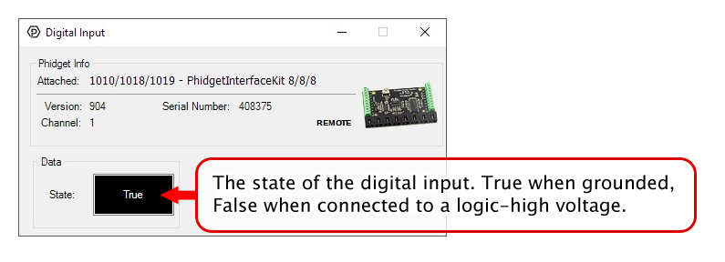
In your Control Panel, double click on "Digital Input":
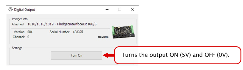
In your Control Panel, double click on "Digital Output":
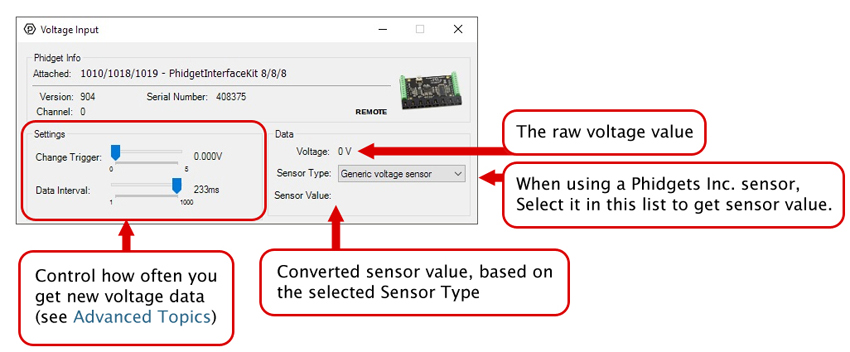
In your Control Panel, double click on "Voltage Input":
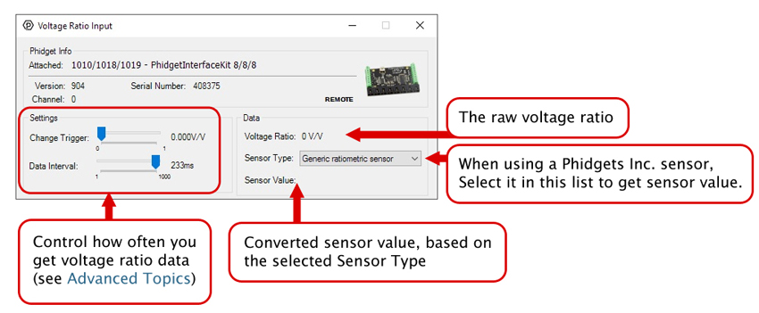
In your Control Panel, double click on "Voltage Ratio Input":
Before you open a Phidget channel in your program, you can set these properties to specify which channel to open. You can find this information through the Control Panel.
1. Open the Control Panel and double-click on the red map pin icon:

2. The Addressing Information window will open. Here you will find all the information you need to address your Phidget in your program.

See the Phidget22 API for your language to determine exact syntax for each property.
Note: Graphing and logging is currently only supported in the Windows version of the Phidget Control Panel.
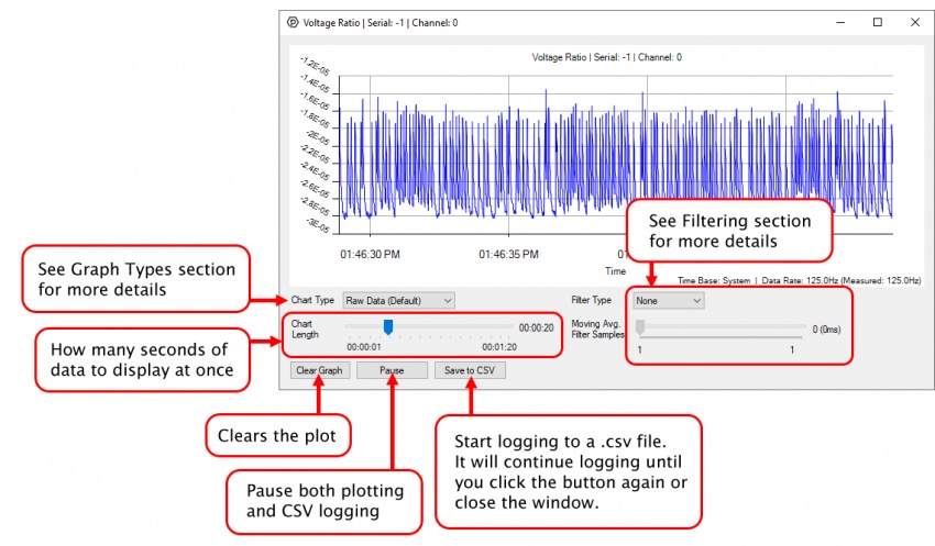
In the Phidget Control Panel, open the channel for your device and click on the ![]() icon next to the data type that you want to plot. This will open up a new window:
icon next to the data type that you want to plot. This will open up a new window:
If you need more complex functionality such as logging multiple sensors to the same sheet or performing calculations on the data, you'll need to write your own program. Generally this will involve addressing the correct channel, opening it, and then creating an Event Handler and adding graphing/logging code to it.
The quickest way to get started is to download some sample code for your desired programming language and then search google for logging or plotting in that language (e.g. "how to log to csv in python") and add the code to the existing change handler.
You can perform filtering on the raw data in order to reduce noise in your graph. For more information, see the Control Panel Graphing page.
You can perform a transform on the incoming data to get different graph types that may provide insights into your sensor data. For more information on how to use these graph types, see the Control Panel Graphing page.
The Change Trigger is the minimum change in the sensor data needed to trigger a new data event.
The Data Interval is the time (in ms) between data events sent out from your Phidget.
The Data Rate is the reciprocal of Data Interval (measured in Hz), and setting it will set the reciprocal value for Data Interval and vice-versa.
You can modify one or both of these values to achieve different data outputs. You can learn more about these properties here.
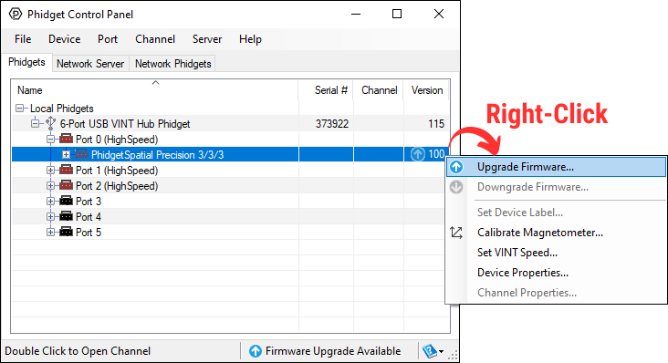
Firmware Upgrade
MacOS users can upgrade device firmware by double-clicking the device row in the Phidget Control Panel.
Linux users can upgrade via the phidget22admin tool (see included readme for instructions).
Windows users can upgrade the firmware for this device using the Phidget Control Panel as shown below.
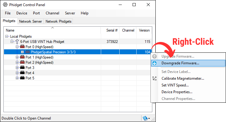
Firmware Downgrade
Firmware upgrades include important bug fixes and performance improvements, but there are some situations where you may want to revert to an old version of the firmware (for instance, when an application you're using is compiled using an older version of phidget22 that doesn't recognize the new firmware).
MacOS and Linux users can downgrade using the phidget22admin tool in the terminal (see included readme for instructions).
Windows users can downgrade directly from the Phidget Control Panel if they have driver version 1.9.20220112 or newer:
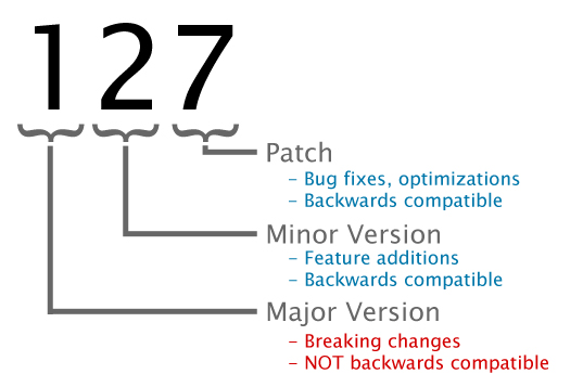
Firmware Version Numbering Schema
Phidgets device firmware is represented by a 3-digit number. For firmware patch notes, see the device history section on the Specifications tab on your device's product page.
If you want to know more about the capabilities of the analog inputs on this device, check the Analog Input Guide.
If you want to know more about the capabilities of the digital inputs on this device, check the Digital Input Guide.
If you want to know more about the capabilities of the digital outputs on this device, check the InterfaceKit Digital Outputs.
| Channel Name | API | Channel |
|---|---|---|
| Voltage Input | VoltageInput | 0 - 7 |
| Voltage Ratio Input | VoltageRatioInput | 0 - 7 |
| Digital Input | DigitalInput | 0 - 7 |
| Digital Output | DigitalOutput | 0 - 7 |