RFID Guide
Learn more about Phidget RFID interfaces here.
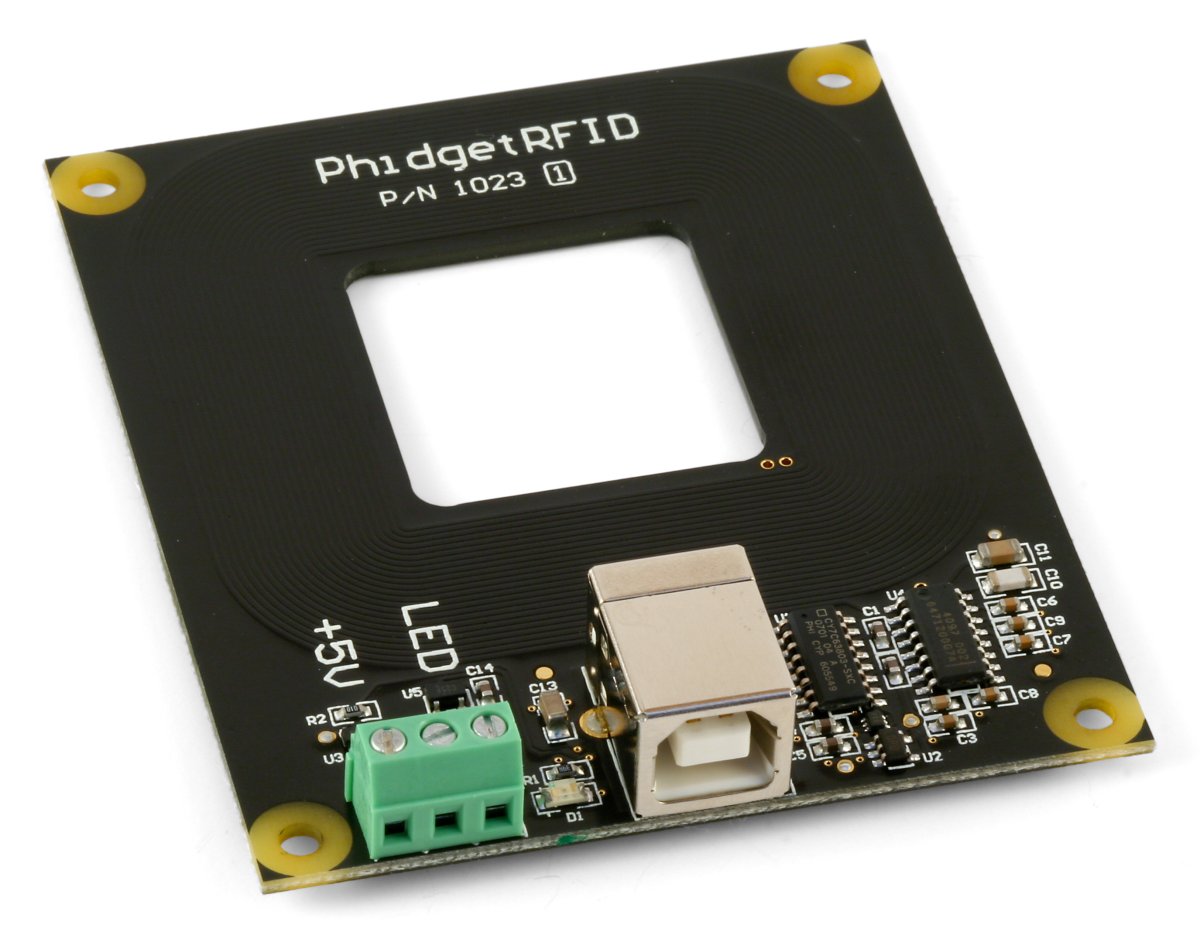
The PhidgetRFID reads RFID tags that are brought in close proximity to the reader and returns the tag identification number.
RFID (radio frequency identification) systems use data strings stored inside RFID tags or transponders) to uniquely identify people or objects when they are scanned by an RFID reader. These types of systems are found in many applications such as passport protection, animal identification, inventory control systems, and secure access control systems.
The PhidgetRFID (as well as the RFID tags sold by Phidgets) uses the EM4102 protocol. Any other tags that also use the EM4102 protocol can be used with the PhidgetRFID reader.
Because passive tags require a strong RF field to operate, their effective range is limited to an area in close proximity to the RFID reader. The distance over which the RFID tag is usable is affected by such things as the tag shape and size, materials being used in the area near the reader, and the orientation of the reader and tag in respect to each other and in their operating environment. The smaller a tag, the closer it must be to the reader to operate.
| RFID Reader | |
|---|---|
| API Object Name | RFID |
| Antenna Output Power Max | 10 μW |
| Antenna Resonant Frequency Min | 125 kHz |
| Antenna Resonant Frequency Max | 140 kHz |
| Supported Protocols | EM4102 |
| Read Rate | 33 ms |
| USB Speed | Low Speed |
| Electrical Properties | |
| Available External Voltage (+5V) | 5 V DC |
| Available External Voltage (LED) | 5 V DC |
| Available External Current (+5V) | 400 mA |
| Available External Current (LED) | 16 mA |
| Output Impedance (LED) | 250 Ω |
| Current Consumption Min | 16 mA |
| Current Consumption Max | 100 mA |
| Physical Properties | |
| Recommended Wire Size | 16 - 26 AWG |
| Operating Temperature Min | 0 °C |
| Operating Temperature Max | 70 °C |
| Digital Outputs | |
| Number of Digital Outputs | 2 |
| Digital Output Voltage Min | 0 V DC |
| Digital Output Voltage Max | 5 V DC |
| Customs Information | |
| Canadian HS Export Code | 8471.80.00 |
| American HTS Import Code | 8471.80.40.00 |
| Country of Origin | CN (China) |
| Device | Object Name | Channel |
|---|---|---|
| RFID Reader | RFID | 0 |
| 5V Digital Output | DigitalOutput | 0 |
| LED Output | DigitalOutput | 1 |
| On-board LED | DigitalOutput | 2 |
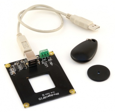
Welcome to the 1023 user guide! In order to get started, make sure you have the following hardware on hand:
Next, you will need to connect the pieces:
Now that you have everything together, let's start using the 1023!
In order to demonstrate the functionality of the 1023, the Phidget Control Panel running on a Windows machine will be used.
The Phidget Control Panel is available for use on both macOS and Windows machines.
To open the Phidget Control Panel on Windows, find the ![]() icon in the taskbar. If it is not there, open up the start menu and search for Phidget Control Panel
icon in the taskbar. If it is not there, open up the start menu and search for Phidget Control Panel
To open the Phidget Control Panel on macOS, open Finder and navigate to the Phidget Control Panel in the Applications list. Double click on the ![]() icon to bring up the Phidget Control Panel.
icon to bring up the Phidget Control Panel.
For more information, take a look at the getting started guide for your operating system:
Linux users can follow the getting started with Linux guide and continue reading here for more information about the 1023.
After plugging the 1023 into your computer and opening the Phidget Control Panel, you will see something like this:
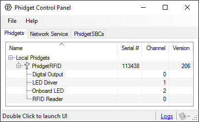
The Phidget Control Panel will list all connected Phidgets and associated objects, as well as the following information:
The Phidget Control Panel can also be used to test your device. Double-clicking on an object will open an example.
Double-click on the RFID object labelled RFID Reader in order to run the example:
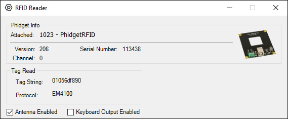
General information about the selected object will be displayed at the top of the window. You can also experiment with the following functionality:
Double-click on one of the Digital Output objects available in order to run the example. They are labelled Digital Output, LED Driver, and Onboard LED.
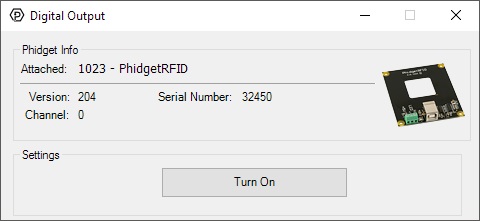
General information about the selected object will be displayed at the top of the window. You can also experiment with the following functionality:
Before you can access the device in your own code, and from our examples, you'll need to take note of the addressing parameters for your Phidget. These will indicate how the Phidget is physically connected to your application. For simplicity, these parameters can be found by clicking the button at the top of the Control Panel example for that Phidget.

In the Addressing Information window, the section above the line displays information you will need to connect to your Phidget from any application. In particular, note the Channel Class field as this will be the API you will need to use with your Phidget, and the type of example you should use to get started with it. The section below the line provides information about the network the Phidget is connected on if it is attached remotely. Keep track of these parameters moving forward, as you will need them once you start running our examples or your own code.

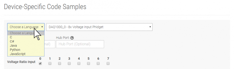
You are now ready to start writing your own code for the device. The best way to do that is to start from our Code Samples.
Select your programming language of choice from the drop-down list to get an example for your device. You can use the options provided to further customize the example to best suit your needs.
Once you have your example, you will need to follow the instructions on the page for your programming language to get it running. To find these instructions, select your programming language from the Programming Languages page.
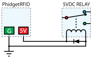
The PhidgetRFID has four outputs - two of which are available to the user. Output 0 is a 5VDC source from the USB bus through a P-Channel MOSFET with less than one ohm impedance. This can be used to switch a TTL or CMOS device, or it can be used to drive a 5VDC relay such as the Aromat JS1-5V. Output 1 is an LED drive output at 5VDC with maximum 15mA of available current (250 ohm CMOS output). Both Output 0 and 1 are available in hardware at the terminal blocks on the PhidgetRFID board. If Output 0 is used to drive a relay, a fast clamping diode must be placed across the relay drive pins as shown in the diagram on the right. Not doing so can result in permanent damage to the PhidgetRFID board.
| Output | Function | Connection |
| 0 | +5VDC Source | Terminal Block |
| 1 | External LED Drive | Terminal Block |
| LED | Internal LED Drive | Internal Only |
| RF Enable | RF Antenna Enable | Internal Only |
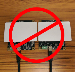
If you are using multiple RFID readers, placing them too close together will cause interference when reading tags. You can work around this problem by rapidly "polling" each 1023 by turning the antenna on, checking for tags, and then turning it off in sequence. Of course, this will lengthen the amount of time it takes for your system to read a tag, since you may have to wait for the nearest reader to become active.
When trying to read tags, you should allow the tag to remain within detection range for at least 50ms. Tags moving through the detection area faster than this may not register.
For more information on RFID readers and tags, visit the RFID Guide.
| Channel Name | API | Channel |
|---|---|---|
| RFID Reader | RFID | 0 |
| Digital Output | DigitalOutput | 0 |
| LED Driver | DigitalOutput | 1 |
| Onboard LED | DigitalOutput | 2 |
| API | Detail | Language | OS | |
|---|---|---|---|---|
| RFID | Visual Studio GUI | C# | Windows | Download |
| RFID | Objective-C | macOS | Download | |
| RFID | Swift | macOS | Download | |
| RFID | Swift | iOS | Download | |
| RFID | Visual Basic | Windows | Download | |
| RFID | Max | Multiple | Download | |
| DigitalOutput | Visual Studio GUI | C# | Windows | Download |
| DigitalOutput | Objective-C | macOS | Download | |
| DigitalOutput | Swift | macOS | Download | |
| DigitalOutput | Swift | iOS | Download | |
| DigitalOutput | Visual Basic | Windows | Download | |
| DigitalOutput | Max | Multiple | Download |
| Date | Board Revision | Device Version | Comment |
|---|---|---|---|
| June 2002 | 0 | 103 | Product Release |
| April 2004 | 0 | 200 | Onboard LED, 2 Digital Outputs added. Ability to enable/disable Antenna added. |
| January 2005 | 0 | 201 | RF Circuitry upgraded to improve reliability |
| January 2006 | 0 | 202 | Onboard microprocessor upgraded to Flash version. |
| September 2006 | 0 | 203 | Changed enable functionality to re-initialize reader |
| June 2006 | 0 | 204 | Low Voltage Reset set at 4.7 Volts |
| April 2007 | 0 | 205 | Protocol parsing bug fixed which garbled top 3 bits of RFID Tag. |
| July 2007 | 1 | 206 | Unused internal I/O pulled high out of an abundance of caution, bus current characterized. Terminal block moved to edge of PCB, center of antenna routed out, digital output transients on startup eliminated. |
| June 2013 | Product Discontinued. Succeeded by the 1024 - PhidgetRFID Read/Write. The 1024 differs from the 1023 in its ability to write to compatible tags, and to read tags belonging to a number of additional protocols. | ||