Load Cell Correction
Squeezing every last bit of accuracy out of your load cells
by James
Introduction
Load cells are a good way to measure forces on an object to a high degree of accuracy. However, there are some factors you will have to keep in mind to get the best results out of your load cells.
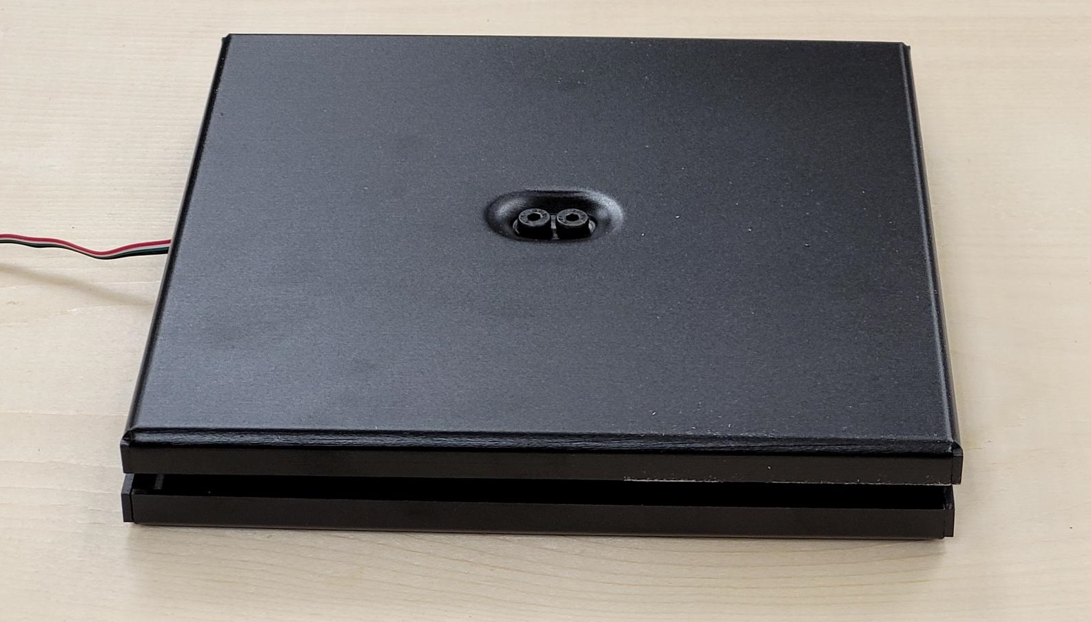
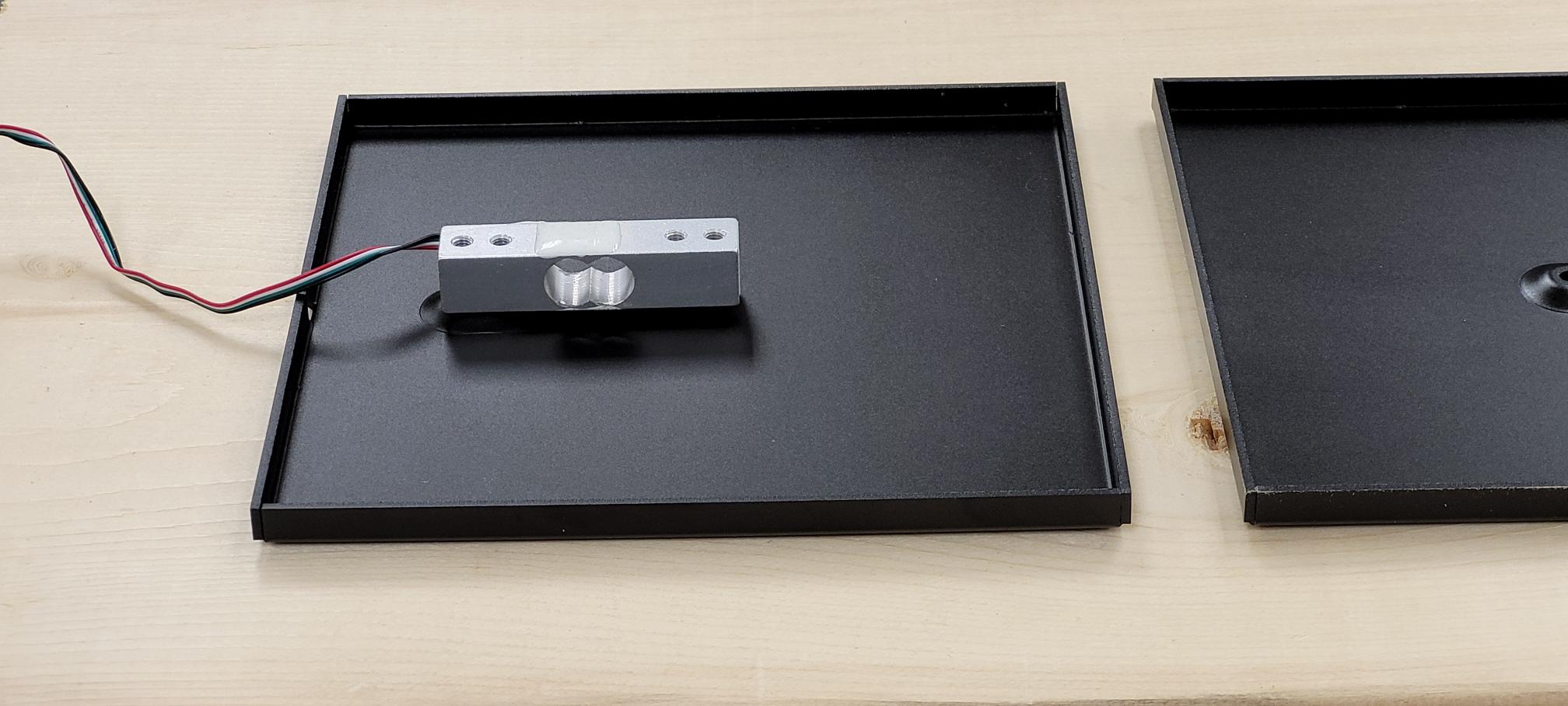
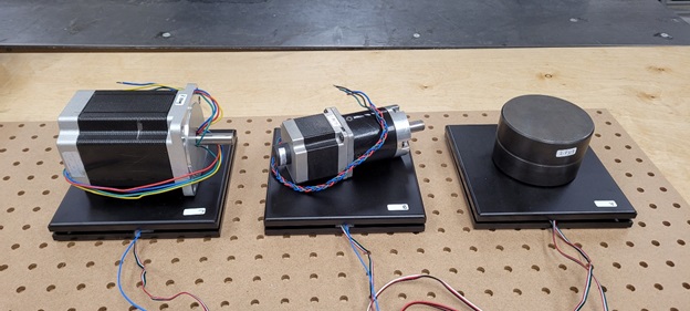
To demonstrate some of these effects, we have used a number of KIT4007 Weighing Scale Kits equipped with 5kg load cells as a common platform, each paired with a DAQ1500 Wheatstone Bridge Phidget.
To be able to use your load cells in any meaningful way, you will need to calibrate your load cell in its environment. This means establishing a baseline offset for your sensor, as well as determining the scale factor for converting the sensor’s raw V/V measurement into something more useful, such as kilograms. If you haven’t already, please first check our guide on Calibrating Load Cells, then come back here.
For simplicity’s sake, and to help give the numbers in this article some tangible meaning, all load cell readings in this article have been converted to grams or kilograms as best suits the example.
Once you have calibrated your load cell, you are good to go for short term applications, on a time scale you might expect from a kitchen scale. Simply zero the scale before use, and you will get a fairly accurate reading of the weight on the scale.
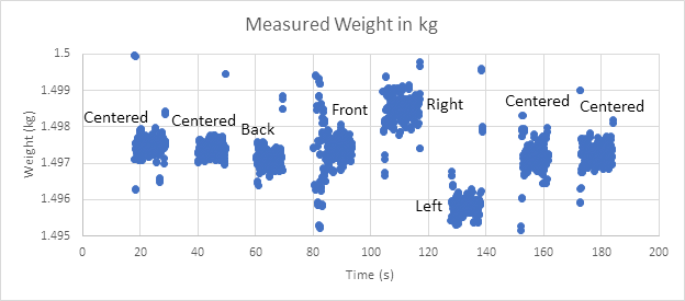
There is one caveat here: for best results, the weight must be applied to the center of the scale. More generally, the force applied to a load cell should always be as in-line with the sensing axis as possible. The following graph (Fig1) demonstrates the effect of placing and removing a weight in various areas of a scale’s surface. Outside of the expected shocks when adding or removing the weight, the results are very consistent so long as the weight is placed on the same part of the scale.
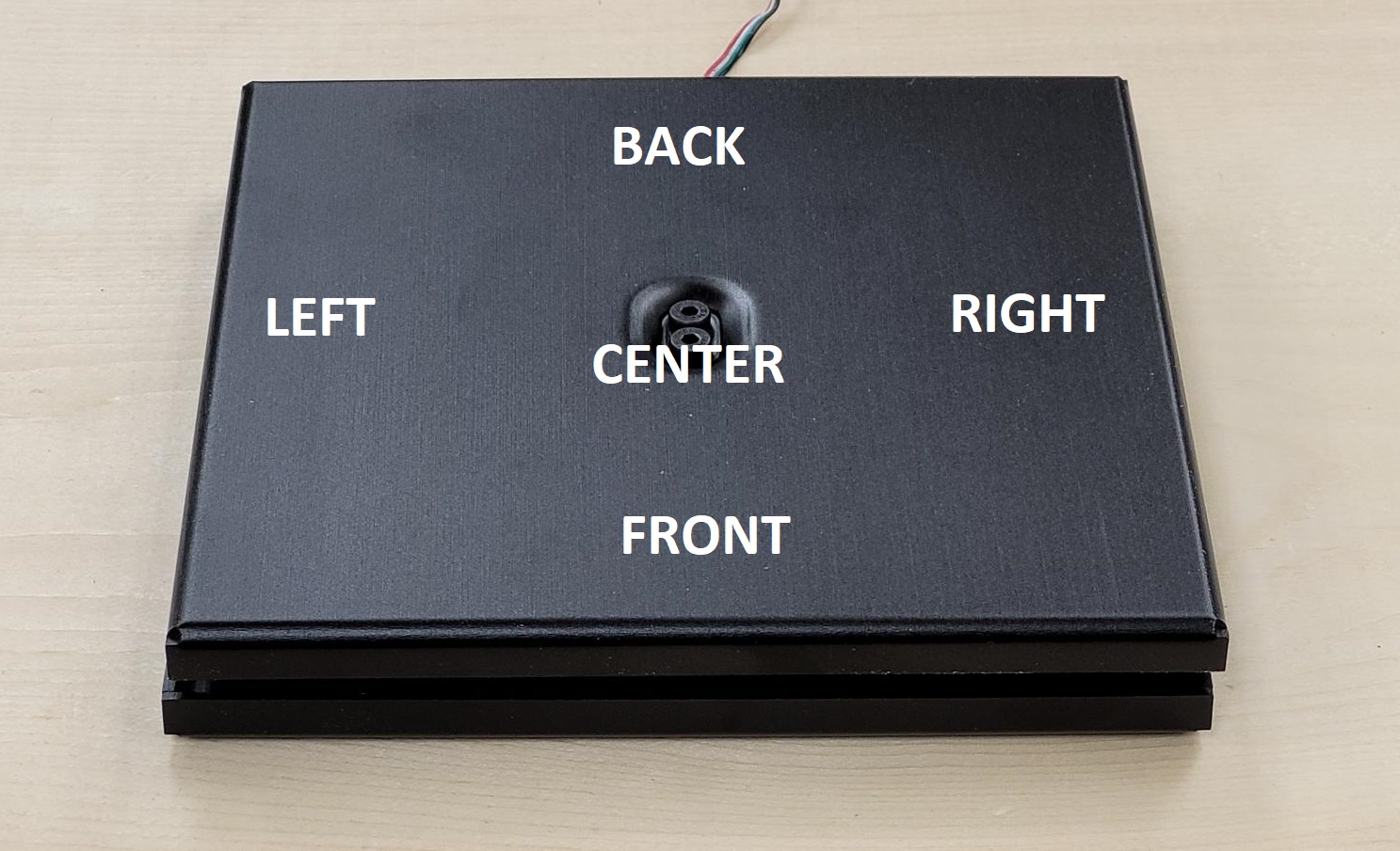
If your application can be easily zeroed before each use, you may safely ignore the following
Running a Load Cell for Longer Timeframes
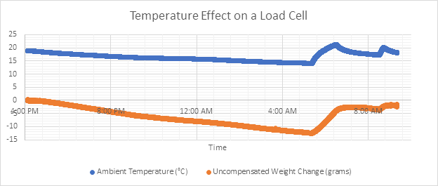
Things get a bit more interesting if you want to run a load cell over longer periods of time. Load cells are slightly sensitive to temperature to a degree that varies from load cell to load cell, depending on manufacturing variations. If you want your scale to be as accurate as possible for hours or days, you will need to compensate for this temperature effect. Even changes to room temperature throughout the day can have a visible effect on the measurements from the sensor. (Fig2)
Our testing has shown that this effect shows up primarily as an offset, meaning the amount of change will be the same regardless of the amount of weight on the load cell. This makes calculating the compensation factor as easy as leaving the scale out for a day and measuring changes against temperature.
For the simplest temperature compensation calculation, choose two points in the data you collect (preferably separated by the largest difference in temperature) and divide the change in load cell V/V by the change in temperature. You now have the load cell’s temperature compensation coefficient (we’ll call it Mtemp).
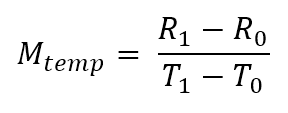
- R0 and R1 are the readings from the load cell, in the case of the DAQ1500 these will be in V/V
- T0 and T1 are the temperatures that the readings R0 and R1 were taken at, respectively.
Any time you use the scale, you can read the temperature of the load cell and multiply the difference in temperature from your temperature reference, and add the result to your load cell’s measurement.
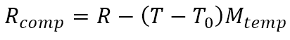
- T0 is the temperature at which you last zeroed your load cell
- T is the current temperature
- R is the current reading from the load cell
- Rcomp is the temperature compensated reading from the load cell
To apply temperature compensation and load cell calibration all in one step we get:
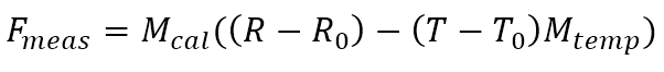
- Fmeas is the actual force measured by the load cell
- Mcal is the calibration gain to convert raw measurements to a real value
- R0 is the sensor’s offset
- T0 is the temperature of the sensor when it was zeroed
This all seems easy enough, just put a temperature sensor beside your weigh-scale and be off to the races, right?
Not quite.
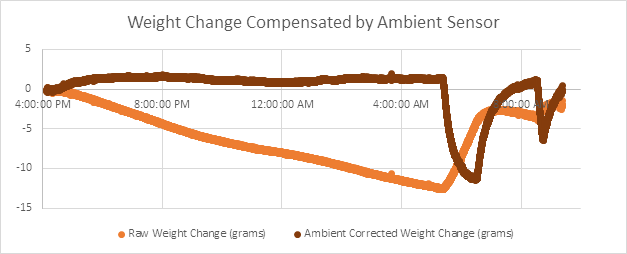
From Fig3, we can see the ambient temperature sensor works quite well to counter the temperature effect during periods of slow temperature change, but the correction falls apart with faster changes (such as when the heater kicks in for the morning). When the temperature of the room changes quickly, the ambient temperature sensor will track the temperature of the air much more closely than the much heavier weigh-scale. The resulting effect is that temperature compensating against an ambient temperature sensor can lose track of the temperature of the load cell itself, resulting in similarly bad (and arguably worse) results.
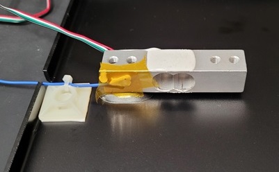
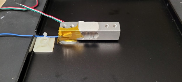
So what options do we have for tracking the load cell directly? For easy use with Phidgets, there are two main options: thermocouples and RTDs. Both of these sensors can have probes in small enough form factors to be pasted directly onto the load cell itself. We used Kapton tape with a blob of thermal paste. Be sure to attach your temperature probe on the static (not moving) side of the load cell.
For a wider experiment, we pasted thermocouples and a small RTD onto the load cells on a few scales, and measured them overnight to compare the results. For all of our experiments, we averaged a second of data from each sensor as a moving average filter.
Specifically we used an RTD plugged into a TMP1200, and two thermocouples with a TMP1101.
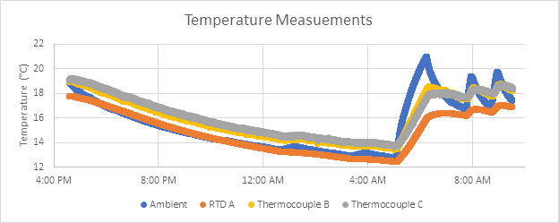
To give a frame of reference for the conditions of our test, we can first display the temperatures collected for the duration of the test. (Fig4) While there is some offset variation from sensor to sensor, the main takeaway here is that all load cells experienced a similar degree of temperature change overnight.
Another point to note is how much slower the load cell temperatures change compared to the ambient temperature of the room.
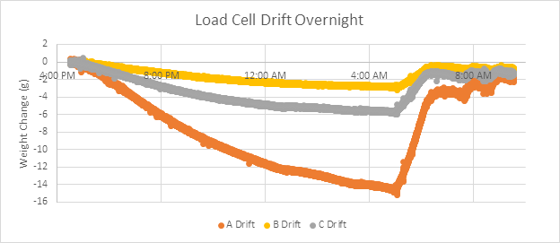
By graphing the raw (converted to grams) changes in load cell measurement (Fig5), we can see there are significant differences in temperature sensitivity from load cell to load cell. In our experiment, load cell A changed by 15g at the coldest part of the night, while load cells B and C are only affected by 3g and 6g respectively. If you want to temperature-compensate your load cells, each load cell in your system will need to be temperature compensated individually.
The following graphs (Fig6, Fig7, and Fig8) show temperature correction on all three scales (A, B, and C), where scale A is compensated using an RTD, while B and C are compensated using thermocouples. These graphs represent the change in the measured value in grams from the initial measurement taken by the scale. The scales are each weighted down by varying degrees to demonstrate that the temperature compensation process remains the same independent of load. (A: 2.8kg, B: 1.5kg, C: 3.5kg)
Each graph has three sets of data, comparing readings with no compensation (Raw), compensation with an ambient temperature sensor (Ambient) and compensation with a more direct probe (RTD or Thermocouple)
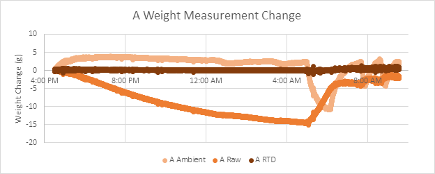
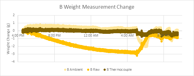
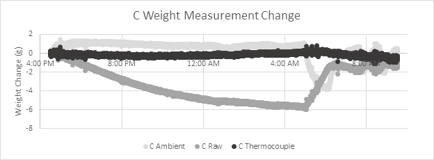
By directly probing the temperature of the load cell, the temperature correction more closely follows the temperature of the sensing components, allowing temperature effects to be all-but eliminated.
As a quick reminder that we are compensating for an already very small effect, consider these scales are all using 5kg load cells, which means the worst case uncompensated error measured here is 0.3% of full-scale over 5°C. With temperature compensation, this has been reduced to 1 gram of error as a worst-case on all scales, or 0.02% full scale.
One last recommendation is that if you are planning to temperature compensate your load cells, we recommend using small RTD resistors in place of thermocouples for this application, as the RTD will result in more consistent results.
Load Cell Self-Heating?
Due to the construction of load cells as effectively a set of resistors, it is easy to imagine these sensors could have a problem with self-heating if left on for enough time. However, through the course of collecting data for this article, we can safely conclude that any self-heating effects are dwarfed by changes in room temperature.
In more certain terms: self-heating is not a large contributor to load cell drift over time.
Conclusions
If you are planning to use your load-cell for periods ranging from a few seconds to 5 minutes at a time between zeroing the scale, the load cell will have very predictable and repeatable results without the need for additional processing. If you plan to run your load cells for longer periods of time, we recommend using a temperature probe, preferably a small RTD (though a thermocouple will also work), to measure the temperature of the load cell directly for temperature compensation. This will ensure consistent results without the need to re-zero the load cell every few minutes.