Products for USB Sensing and Control

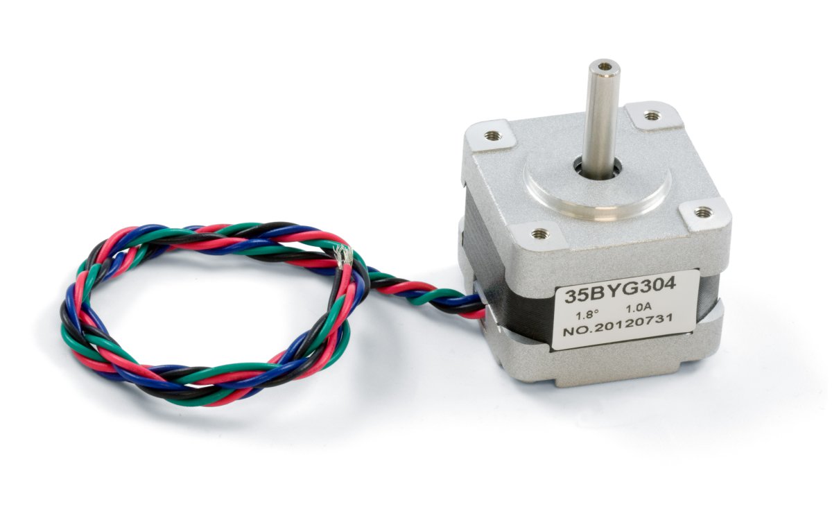
This motor is a little bit larger than the 3300 but with a shorter length. It also produces twice the torque. The motor is also very efficient in converting current into torque and velocity.
| Motor Properties | |
|---|---|
| Motor Type | Bipolar Stepper |
| Manufacturer Part Number | 35BYG304 |
| Step Angle | 1.8° |
| Step Accuracy | 5 % |
| Holding Torque | 1.3 kg·cm |
| Rated Torque | 1.1 kg·cm |
| Maximum Speed (w/1063 Motor Controller) | 600 RPM |
| Maximum Motor Speed | 4688 RPM |
| Acceleration at Max Speed (w/1067 Motor Controller) |
2.4E+06 1⁄16 steps/sec² |
| Electrical Properties | |
| Recommended Voltage | 12 V DC |
| Rated Current | 1 A |
| Coil Resistance | 3.5 Ω |
| Phase Inductance | 3.5 mH |
| Physical Properties | |
| Shaft Diameter | 5 mm |
| Mounting Plate Size | NEMA - 14 |
| Weight | 130 g |
| Number of Leads | 4 |
| Wire Length | 300 mm |
| Customs Information | |
| Canadian HS Export Code | 8501.10.00 |
| American HTS Import Code | 8501.10.40.60 |
| Country of Origin | CN (China) |
The 3301 stepper motor connects to a bipolar motor controller such as the 1067 - PhidgetStepper Bipolar HC.
Motors with Black, Green, Red, and Blue wires
The following table shows how to connect the motor wires to the board connectors to produce a clockwise rotation in the stepper motor when increasing position. To wire for counter-clockwise rotation when increasing position, reverse the red and blue wires.
| Wire Color | Black | Green | Red | Blue |
|---|---|---|---|---|
| Board Connector | A | B | C | D |
Motors with Blue, Green, Yellow, and Red wires
The following table shows how to connect the motor wires to the board connectors to produce a clockwise rotation in the stepper motor when increasing position. To wire for counter-clockwise rotation when increasing position, reverse the yellow and blue wires.
| Wire Color | Yellow | Blue | Green | Red |
|---|---|---|---|---|
| Board Connector | A | B | C | D |
Note: Make sure to unplug the power cord from the motor controller before switching wires around.

|
Connecting the motor directly to a power supply will destroy the motor and void the warranty. If you want to check your motor make sure it is connected to a constant current / chopper drive controller. |