Stepper Motor and Controller Guide
Introduction
Stepper motors are broadly available motors commonly used for positioning. The rotor of a stepper moves in a series of discrete steps. By energizing the coils of the motor in sequence through many of these steps, the direction of rotation, number of rotations, and exact position of the motor shaft can be easily controlled. By controlling the time between the steps, the speed and acceleration of the stepper is regulated. In contrast, a DC motor will blindly spin at the highest speed possible when powered, unless it is controlled with an encoder and a control system program. It is not necessary to use an encoder on a stepper motor unless you're concerned about the motor losing count of the steps over a long period of time or in high torque situations.
Each stepper motor is designed to move by a certain angle with each discrete step. The simplest stepper motors will rotate 90° per step. Standard industrial steppers will rotate 1.8° per step. The stepping angle can be further reduced through use of a gearbox.
In addition to the ease of precisely controlling position and speed, Steppers have other advantages:
- Most motors have very little torque when they are operating at low speed or standstill. Since a stepper’s rotor is held in place by a magnetic field during each step, steppers have full torque at low speed or standstill, making them very useful for low speed rotation and actuation. Additionally, a stepper motor can remain in a fixed position for long periods of time with the rated current in the windings, whereas with DC motors, stalling and remaining in a fixed position for long periods of time will cause motor burnout.
- DC Motors have brushes with a finite lifetime. Steppers have no brushes, and are limited only by the life of the bearings.
Compared to DC Motors, there are disadvantages to Steppers:
- Each step will produce vibration in the motor. If these vibrations are at the mechanical resonant frequency of the motor, they can cause the rotor to overshoot and bounce back and forth, resulting in a severe loss of torque. This phenomenon is called “ringing” and is often accompanied by a loud buzzing or grinding noise. To prevent the motor from operating in such a way, you should test the motor at various speeds in the physical application it is intended for, and try to avoid running the motor at a speed which exhibits ringing behaviour.
- If the motor encounters a brief overload, the fixed coils on the stator and the free-spinning rotor can lose track of each other. If this happens at higher speeds, the motor will often stall. Even at lower speeds, your system will have lost track of where exactly the motor is positioned – unless there is an independent system (e.g., an optical encoder) tracking the position.
- A stepper motor cannot be loaded at its maximum torque, as it will almost certainly be overloaded during operation. A DC Motor will naturally adjust its speed depending on how much power is provided, and the torque required to turn it’s shaft.
For more information about the differences between stepper motors, DC motors, and servo motors, see the Motor Selection Guide.
Types of Stepper Motors
We find it useful to classify motors according to how the coils are wound (Bipolar/Unipolar), the internal magnetic construction (Permanent Magnet / Hybrid), and how the current in the coils is regulated (Chopper Drive / Resistive Limited).
Coils
Bipolar
These motors are manufactured with two coils of wire, resulting in one winding per phase. By alternating the power between coils, as well as the direction of the current, the motor is rotated. This configuration produces magnetic fields within the coils in either direction, hence the term “Bipolar.” The controller is more expensive because it has to be able to produce both positive and negative electrical currents, but the advantage is that the entire coil is being used, thus increasing torque capabilities at all speeds. We do not recommend using a bipolar controller to run a unipolar motor, even though it is theoretically possible.
Unipolar
In a unipolar motor, the motor windings consist of two identical coils per phase, wound in opposite directions (each occupying half of the space a coil normally would in a bipolar stepper). As a result, the controller only needs to select which of the two coils to pass current through in order to change the magnetic polarity, and only a positive current is required to be generated. Due to this simplified control mechanism which uses only half of each coil, the torque of unipolar motors are usually much lower, but the overall cost of the system is much cheaper. The simplicity of the unipolar controller also means that you cannot use it to run a bipolar stepper motor.
Magnets
Permanent Magnet
Permanent magnet motors are small, low torque, and inexpensive. They use a permanent magnet in the rotor that is attracted or repelled by magnetic field generated by the stator coils. Step angles are often 7.5° or 15°, and the motors are usually unipolar.
Variable Reluctance
The rotor of a variable reluctance stepper is made of iron, and it therefore aligns with the magnetic field generated by the stator coils. Since it doesn’t use a permanent magnet, it doesn’t matter which direction the current flows as long as each coil is wound in the opposite direction as the coil across from it. Therefore, variable reluctance steppers are unipolar and are typically designed to have larger step angles of 15° or more degrees.
Hybrid
Hybrid Motors dominate the stepper motor world – they use a combination of characteristics from permanent magnet and variable reluctance steppers and have the best torque and speed, but are more expensive to produce. Step angles are typically 0.9° to 3.75°, giving much better step resolution.
Drive
Chopper Drive
Chopper Drive is an electronic control technique which allows specific motors to produce more power, torque, speed, and be more efficient. Instead of relying on the resistance of the coil wiring, the inductance of the wiring is exploited by sophisticated control electronics as a short-term limitation of motor current. Motor Manufacturers don't do a good job of distinguishing motors suitable for use with Chopper Drive electronics. The motors will often be large, square, with very low resistance.
Resistive Limited
Small, inexpensive steppers are designed to be built and controlled as cheaply as possible. To simplify the control electronics, the length and thickness of the wire in the coils is selected for a particular control voltage. This allows the coil itself to regulate the power available to the motor – provided the appropriate voltage is used, of course. We call this type of motor Resistive Limited.
How it Works
Hybrid Bipolar Steppers
This section of the guide will cover the general principle of operation for stepper motors. While this information is by no means necessary to use a stepper motor, those who are curious about their inner workings may read on.
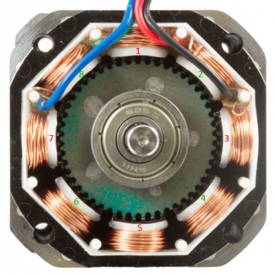
The image to the right is a cross-sectional view of the inside of a hybrid bipolar stepper motor. As you can see, it has eight poles with six teeth each. This motor contains two coils- one wrapping the odd-numbered poles, and the other wrapping the even-numbered poles. The steel end-cap in the center of the image covers a cylindrical permanent magnet which surrounds the shaft.
If positive current is sent to the odd-numbered coil, poles 1 and 5 are magnetized as south, and poles 3 and 7 are magnetized as north. Assuming the permanent magnet in the center of the motor has its north pole facing toward us, this will result in the rotor turning so that the teeth line up with stator poles 1 and 5, as they are in the image. At the same time, poles 3 and 7 will become aligned on the opposite end of the motor, where the gear on the rotor is permanently offset by the width of one tooth and the permanent magnet has magnetized the rotor as south. The rotation of the motor is continued by sending negative current through the even-numbered phase, then negative current through the odd-numbered phase, then positive current through the even-numbered phase, and so on. The stepper controller can reverse the direction of rotation simply by reversing this sequence.
When a stepper motor becomes engaged in software, and current is applied to the coils, it may abruptly "snap" to the position that the rotor is being held at.
Hybrid Unipolar Steppers
The operation of a hybrid unipolar stepper is very similar to the bipolar stepper described above, except that each pole has two seperate coils wound in opposite directions. This results in four phases which only require positive current to operate. Rather than alternating the direction of current, the motor controller simply sends positive current to the appropriate half of the coil.
Controlling the Stepper Motor
Setting the Current Limit
The current limit is an important control property of stepper controllers. Since many stepper motors have a very low coil resistance, the current through the coils cannot “self-regulate” to a safe level on their own. They require the sophisticated control techniques of a Chopper Drive, which is used in all Phidget stepper controllers. As a result, the maximum current allowed should be explicitly set.
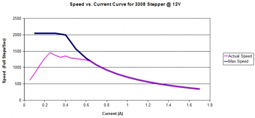
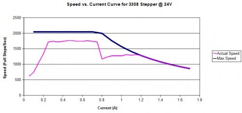
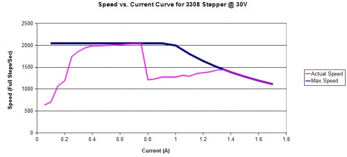
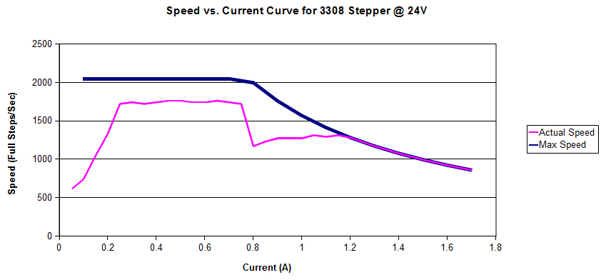
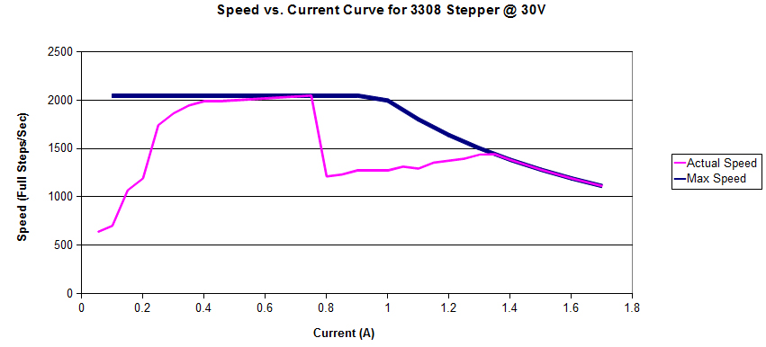
There are many factors that influence what the current limit should be set to. These include, but are not limited to,the acceleration and speed of the stepper, the supply voltage, applied torque, motor inductance, and coil resistance. The process of choosing the current limit can be simplified by following some general rules of thumb. The graphs in this section show a set of speed vs. current characteristics for the 3308 stepper with various power supplies.
In the these graphs, the “actual speed” of the motor is the maximum speed attainable in a real world test done with no load on the motor, but at very high acceleration. The “max speed” shows the limitation on speed imposed by the inductance of the motor coils at a given supply voltage.
When the current limit is set low and the acceleration is high, the motor will not be able to provide enough power to accelerate itself and the load it’s driving. The motor also has to overcome friction losses within the system, and do work on the load - for example, lifting a weight. By increasing the current limit, more current and power is made available to accelerate and maintain maximum speeds. This can be seen on any of the graphs in the initial steep ramp of the actual speed. As the current limit increases, the motor is able to achieve higher speeds.
In the case of this particular motor, the large inductance of the coils - great for producing lots of torque, quickly overwhelms a 12V power supply. To get higher speeds and more performance out of this motor, higher supply voltages are necessary. Compare the actual speed curve on the 12V graph to the 30V graph. At 30V, the motor is able to achieve a much higher speed. It’s important to remember that the actual speed was measured at very high accelerations - by lowering acceleration, higher velocities can be achieved. Of course, if your motor is doing a lot of work, you’ll need to supply enough current to produce the necessary torque, therefore limiting the maximum speed.
Setting Current Limit for your application is a balancing act. By increasing the current limit, more torque is available, but far more power will be consumed when the motor is turning very slowly or stopped. When setting a high acceleration, more power (therefore current) is required to accelerate the motor and it’s load. Selecting the current limit is often done dynamically in the actual application - set the current limit very low, and run the system, increasing the Current Limit if it stalls. After a set up has been determined that is reliable, increase the current limit by another 25% to give some margin.
There is no point in setting the current limit to be greater than the motor’s rated current- the increased inductance will only further limit the motor speed. In this case, the 30V graph shows that it’s not feasible to operate this motor at maximum torque (1.7 Amps) at a speed greater than 1100 full steps per second. By reducing the current limit, greater speeds are possible, but less torque will be available. Most motors designed for Chopper Drive control can operate at much higher voltages, but Phidgets Inc. does not carry a controller that can provide these voltages at this time.
Note that just because you have set the current limit to some amount (for the sake of example let's say 2A) the motor will not draw 2A at all times. The motor will only draw as much current as it needs. This means that if there is only a small load on the motor and it is spinning at less than its top speed the motor might only draw a small fraction of the allotted 2A. Even as low as 300 or 400mA. As more load or higher speed is applied, the current usage will go up until the controller is giving the motor the full current limit. As a motor draws more current, it will also produce more heat. It is normal for a stepper motor to be hot to the touch after running for a while. If the motor is getting very hot, you may be trying to drive too large a load for that particular motor.
Choosing a Supply Voltage
When looking at a stepper motor's specifications, you may come across a "Rated Voltage" value. This value is usually equal to the rated current multiplied by the resistance of the coils of the motor, making it somewhat of a redundant specification. As mentioned earlier, you can increase your controller's supply voltage in order to allow the motor to reach higher speeds at a lower current (because high current causes high inductance which puts a hard limit on how much speed and torque a motor can produce). The motor will also produce more heat as you increase the supply voltage, so it's a good idea to choose a supply voltage based on the performance you need for the motor. Some motors will have a "Recommended Voltage" for a particular controller, which is the amount of voltage needed to reach the optimal speed and torque of the motor with minimal heating.
Setting the Velocity Limit
The velocity of a motor cannot be directly chosen with our stepper controllers. However, a velocity limit can be chosen to ensure that the motor does not go faster than a certain speed. This is useful because every stepper motor has a speed that causes itself to vibrate at the resonant frequency of its own moving parts. When the motor vibrates at this frequency, the motor will often overshoot its target position, causing it to lose most of its torque, sometimes even rotating in the wrong direction. This phenomenon is sometimes called "ringing". If you experience these problems while running your stepper motor at a constant velocity, try setting the velocity limit to lower or higher than it was previously, in an attempt to minimize the amount of time spent operating at this particular velocity.
Setting the Acceleration
The acceleration of a stepper motor is an important consideration when driving a load. Setting the acceleration too high can result in the motor stalling, especially with a heavy load. Try to use low acceleration in high-torque applications.
Continuous Rotation and Forward/Reverse
A stepper motor can be caused to rotate continuously by simply setting the controller's target position property to an extremely large number of steps.
Stepper motors can easily be run in forward or reverse by choosing a target position greater than or less than the current position, respectively. Reversing the polarity of either of the motor's wire pairs will invert this effect- causing a lesser target position to result in forward rotation, and a greater target position to result in reverse rotation. For this reason, you should pay attention to the way you wire a motor when developing and testing code, and ensure that you wire it with the same polarity in the future to avoid erroneous behaviour in applications where rotation direction matters.
Cooling
The stepper controllers sold at Phidgets Inc. have a current rating that is limited by the heat dissipation capability of the board. You could add heatsinks, fans, or other cooling devices to increase the current limit, but do so with caution. Unless you have a way of monitoring the temperature of the driver chip during operation, you have no way of knowing how far beyond the rated specification you can go.
Wire Length
Since the stepper controller is sending a fairly simple signal to the motor, interference is not a big concern. You should be able to have quite long wires between your motor and controller. For more information, see the effects of long wires page.
Saving Power
When the stepper motor has rotated the requested number of steps, and is stopped, the coils will remain energized to hold it in position. This is necessary to allow the motor to support a load on its shaft without rotating to an unknown position.
Holding torque is the amount of torque required to rotate the motor ‘against it’s will’ when the full rated current is flowing through the coils. If power consumption or overheating is a problem, and full holding torque is not required, the Current Limit can be decreased in software when the motor is not moving. Holding torque will decrease linearly as you decrease the Current Limit, but will also allow you to save power and reduce the heat generated in your system.
There is also a small resistance to movement within the motor even when there is no current, called Detent Torque. This may be sufficient to prevent rotation in your application, especially if the stepper has a gearbox on it.
If the motor is not supporting a load or is not required to maintain a specific angle, it is recommended to set the Enable property to false. This will allow the motor shaft to rotate freely, but the present angle may be lost if forces on the motor-shaft are greater than can be resisted by the detent torque of the unpowered motor.
Braking
There are several ways to stop a stepper motor, each with different characteristics:
Set Target Position - If you set the target position to the motor's current position, it will stop. This is typically the best way to stop quickly and hold position, since the motor coils will still be engaged. You could also set the motor velocity limit to zero for a similar effect.
Short the coils - If you have the stepper wires connected to some external circuitry, you could use a switch to short the A and B terminals together, and the C and D terminals together. Due to the Lorentz force of the electrons in the coil, the motor will begin to brake and hold position.
Cut power - You could cut power to the controller, but since the motor coils would no longer be engaged, the momentum would cause it to continue rotating until it slows down from friction and detent.
Stepping Modes
Full Stepping
This is the default mode of stepping for bipolar motors, where both phases of the motor are controlled by two square waves of current. One wave lags behind the other by 90 degrees, and the motion of the motor is locked to these waves. A full step is completed when the square waves advance by 90 degrees. Since both phases are always fully energized, full stepping provides the best torque.
Half Stepping
In this stepping mode, the controller alternates between having one phase energized and both phases energized. This results in the rotor pausing at half-steps in between the poles, effectively halving the step angle. However, since the current to each coil cannot be exactly balanced, the angle that the rotor comes to rest at between poles may not be exactly half the step angle. The downside to half stepping is that the motor will have less torque on the steps when only one phase is energized.
Mini/Micro-stepping
By controlling the the relative current of both phases, the rotor position can come to rest at various equally spaced sub-steps between the two phases. This is achieved by following the same procedure for Full Stepping, except that the current supplied more closely resembles a sine wave rather than a square wave. Some bipolar controllers are designed to micro-step at low speeds to allow for smooth rotation.
Selecting a Gearbox
Using a stepper motor with a gearbox can be a good solution in applications that need very low rotation speeds and/or lots of torque. Selecting a gearbox to attach to the stepper will result in increasing the output torque and decreasing the speed. Simply, the Gearbox Output Speed is:

Although the reduction ratio plays a large part in determining the Gearbox Output Torque, there is also an inefficiency that is introduced through the use of a gearbox. Some of the torque of the motor is internally converted into heat and lost. So to calculate the Gearbox Output Torque:

When choosing a stepper motor with a gearbox, keep in mind that the gearbox is rated to sustain a specific amount of torque, beyond which the gearbox could become damaged. This limit is often much lower than the amount of torque specified by the above equation.
The Gearbox Step Angle can be determined by:

Planetary Gearbox Reduction Ratios

In some applications, it is important to know the exact gear ratio of a gearbox (for example, when you need the output shaft to make a several complete rotations and stop in the same position it started). Most motor datasheets will only list an approximate ratio, like "10:1" or "27:1". However, there are ways to figure out the exact ratio.
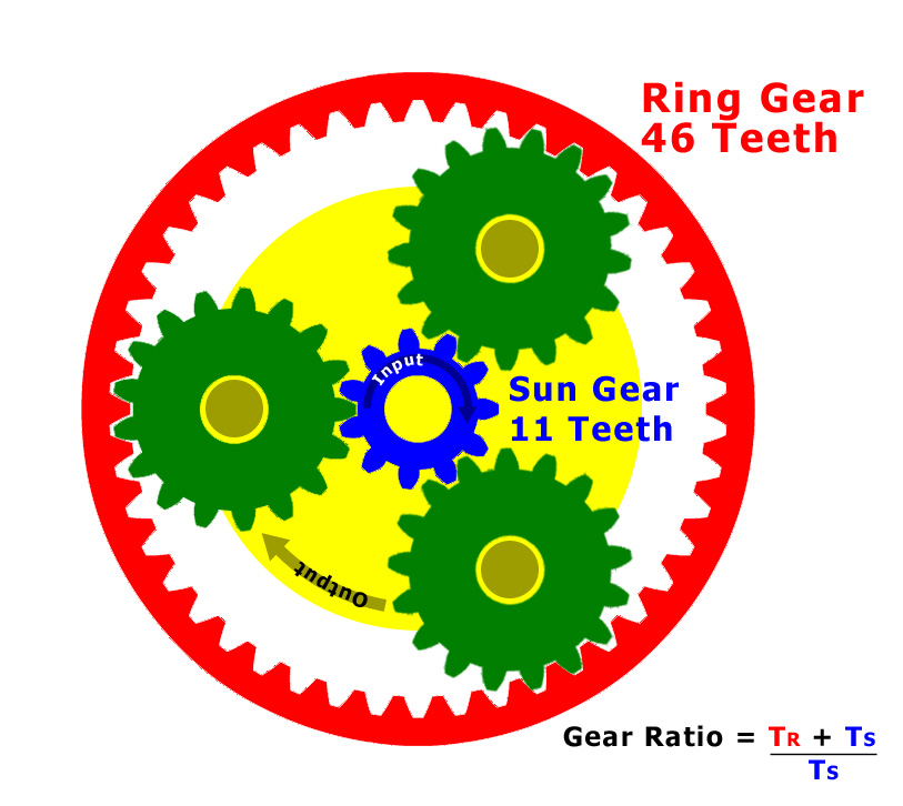
In a planetary gearbox where the sun gear is used as an input and the rotation of the spider linking the planet gears is the output, the reduction ratio can be expressed by the following equation:

Where is the number of teeth on the ring gear, and is the number of teeth on the sun gear. In this situation, the number of teeth on the planetary gears don't affect the reduction ratio and serve only to connect the ring and sun gears. In order to increase the reduction ratio, you need to increase the number of teeth on the ring gear. Since there is limited space inside a motor's gearbox, it eventually becomes impossible to increase the gear ratio. This limitation can be bypassed by introducing multiple gear stages. In a multi-stage planetary gearbox, the axles of the planet gears of the first stage are connected to a piece of metal called a "spider", whose rotation is used to turn the sun of the next stage. It's very common for multi-stage planetary gearboxes to have a tall ring gear that spans multiple stages. To determine the overall reduction ratio of a multi-stage planetary gearbox, simply multiply the two ratios together. For example, two stages each with a 5:1 reduction ratio would result in a total ratio of 25:1. The following table lists exact ratios for gearboxes commonly sold by us:


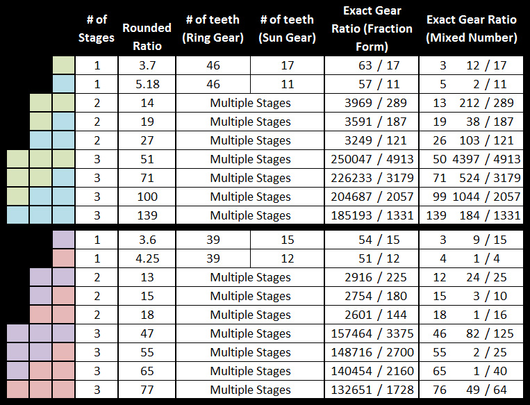
The colored squares visualize the stages that compose each gearbox. For example, a two-stage gearbox with 1 blue and 1 green square indicates that one stage is
the same ratio as the 1-stage gearbox with the green square beside it, and the other stage is the same as the one with a blue square beside it.
If you have a third party gearbox and are unable to open it to count the gear teeth, you could also determine the approximate reduction ratio experimentally by
measuring the rotation angle after a known number of steps have occured. The more accurately you can measure the angle, the better your approximation will be.
Gearbox Terminology
Here is a short list of terms you might come across when deciding upon a gearbox:
Backlash
The amount of clearance between mated gear teeth. Theoretically, the backlash should be “the smaller the better,” but in actual practice, some backlash must be allowed to prevent jamming.
Gear Ratio
The gearbox accepts the power (think of power as a torque that rotates) from the motor, reducing the speed (exactly) by a given ratio, while increasing the torque (roughly) by the same ratio – a ratio of the gear head with which the gear head reduces the motor speed. For example, if a motor has a speed of 500RPM and the reduction ratio is 100:1, the speed of the gear head is 500/100 = 5RPM. This is the actual reduction ratio. The calculated speed from the gear head should be based on this ratio.
Gearbox Step Angle
A full step of the motor will result in the gearbox making a smaller step. The angle of this step is the step angle of the motor divided by the gearbox reduction ratio. For example, a motor with a step angle of 1.8º and a gearbox with a reduction ratio of 20:1 will have a step angle of 1.8/20 = 0.09º at the output of the gearbox.
Gearbox Output Torque
The gearbox takes the torque from the output shaft of the motor, reducing the speed and increasing the torque. The gearbox, depending on its efficiency, loses some of the torque as it is converted into heat. Therefore, the Gearbox Output Torque is the motor output torque multiplied by the reduction ratio multiplied by the efficiency of the gearbox. For example, a motor with a low-speed output torque of 500g*cm and a gearbox with a reduction ratio of 5:1 and 90% efficiency will have a Gearbox Output Torque of 500*5*0.9 = 2.25 kg*cm. Remember, however, that if the Gearbox Output Torque exceeds the allowable torque the gearbox is rated for, you can cause damage to the gearbox.
Gear Trains
Planetary gearboxes use multiple gear sets to achieve large gear reductions. Each gear set makes the gearbox longer, and reduces the efficiency.
Product Comparison Tables
For a full list of stepper motors available from Phidgets.com, see this page:
Glossary of Terms
Motor Terms
Coil Resistance
The electrical resistance (to direct current) of the wiring within the motor. This resistance causes some of the energy being applied to the motor to be converted into heat. Some motors and motor controllers rely solely on the electrical resistance to regulate the current flowing through the motor. The Unipolar Motors we sell, and the 1062 PhidgetStepper Unipolar rely on this inexpensive, but inefficient technique. Other motors will have very low resistance, increasing their efficiency, but requiring very sophisticated control techniques because the resistance cannot regulate the current to a safe level on its own. Our Bipolar controllers and our Bipolar motors use this technique, otherwise known as Chopper Drive.
Holding Torque
Holding Torque is the amount of torque needed to rotate the shaft of the stepper motor while the controller attempts to hold the position, using the maximum current allowed for the motor. Holding Torque is the sum of the magnetic force exerted by the electrical coils to hold the current position, and the detent torque, which is the natural resistance of the motor against rotation due to the permanent magnet inside the motor. Once the motor begins to rotate, the torque it can exert (at least at low speeds) is Holding Torque minus twice the detent torque (because the motor is now working against the detent). As the motor speed increases, torque begins to decrease. If the power supply voltage is low, or the inductance of the motor is high, the torque will fall more rapidly.
Motor Inductance
Stepper motors are built with a specific coil inductance. A high inductance motor will provide a greater amount of torque at low speeds, at the cost of having lower torque at high speeds.
Overhung Load (OHL) / Radial Load
An external load applied on the output shaft of the gearbox. This load is often produced if pulleys are mounted directly on the shaft, pulling perpendicular to it. When the OHL exceeds a safe value, the bearings can fail, or the shaft can break from bending fatigue. While OHL and Thrust Load specifications are only available for our gearbox motors, both types of load should be avoided when using any of our motors.
Rated Current
The rated current is the maximum current that should be applied to each coil of the motor. Current generates heat within the motor, and exceeding the regulated current will cause the motor to overheat. If the motor is operated in a hot environment, or is enclosed, it can overheat at currents lower than the rated current.
Step Angle
The change in the shaft angle when the motor moves forward or backward by one full step.
Step Accuracy
Depending on the motor and how it is loaded down, the step positions will vary slightly. Fortunately, this variance doesn’t accumulate – so if you move the motor by one step or one million steps, the angle that the motor stops at will have the same margin of error.
Thrust load / Axial Load
A load applied directly in line with the output shaft of the gearbox. Avoid thrust as much as possible. If thrust load is unavoidable, keep it to no more than the permissible value.