
Load Cell Correction
Squeezing every last bit of accuracy out of your load cells
by James
Article updated Aug 2026
Introduction
Load cells provide an accurate means of measuring forces on an object or structure. However, there are some factors you will have to keep in mind to get the best results out of your load cells.
To be able to use your load cells in any meaningful way, you will need to calibrate your load cell while assembled in its environment. This means establishing a baseline offset for your sensor, as well as determining the scale factor for converting the sensor's raw V/V measurement into something more useful, such as kilograms. If you haven't already, please first check our guide on Calibrating Load Cells, then come back here.
Short Timeframes
Once you have calibrated your load cell, you are good to go for short-term applications, on a timeframe you might expect from a kitchen scale. Simply zero the scale before use, and you will get a fairly accurate reading of the weight on the scale as long as the mass is centered.
To demonstrate this effect, we have used a KIT4007 Weighing Scale Kit equipped with a 5kg load cell, paired with a DAQ1500 Wheatstone Bridge Phidget.
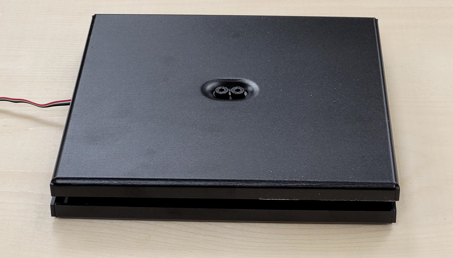
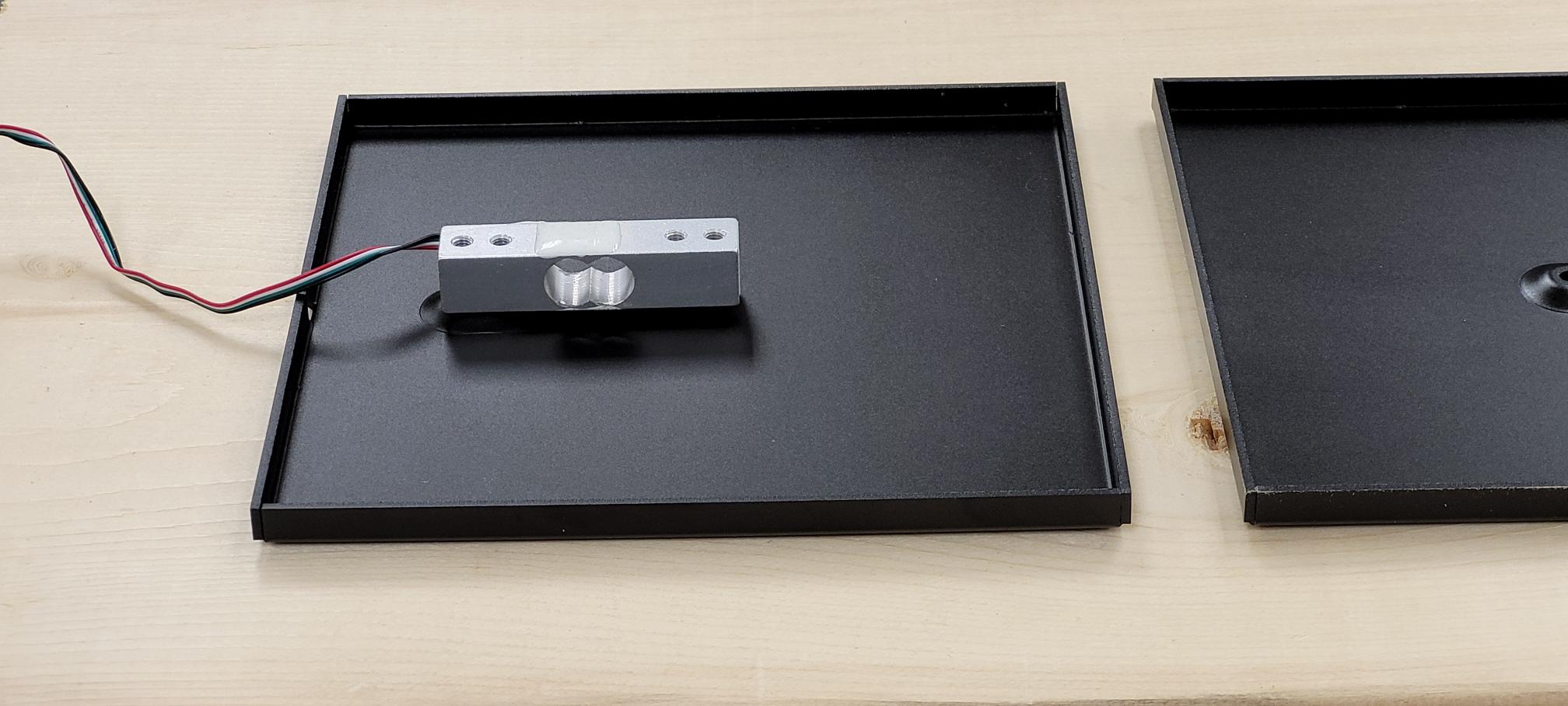
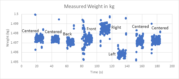
For single load cells that are used in a scale like this, the weight must be applied to the center of the scale. More generally, the force applied to a load cell should always be as in-line with the sensing axis as possible. The following graph (Fig1) demonstrates the effect of placing and removing a weight in various areas of a scale's surface. Outside of the expected spikes when adding or removing the weight, the results are very consistent as long as the weight is placed on the same part of the scale.
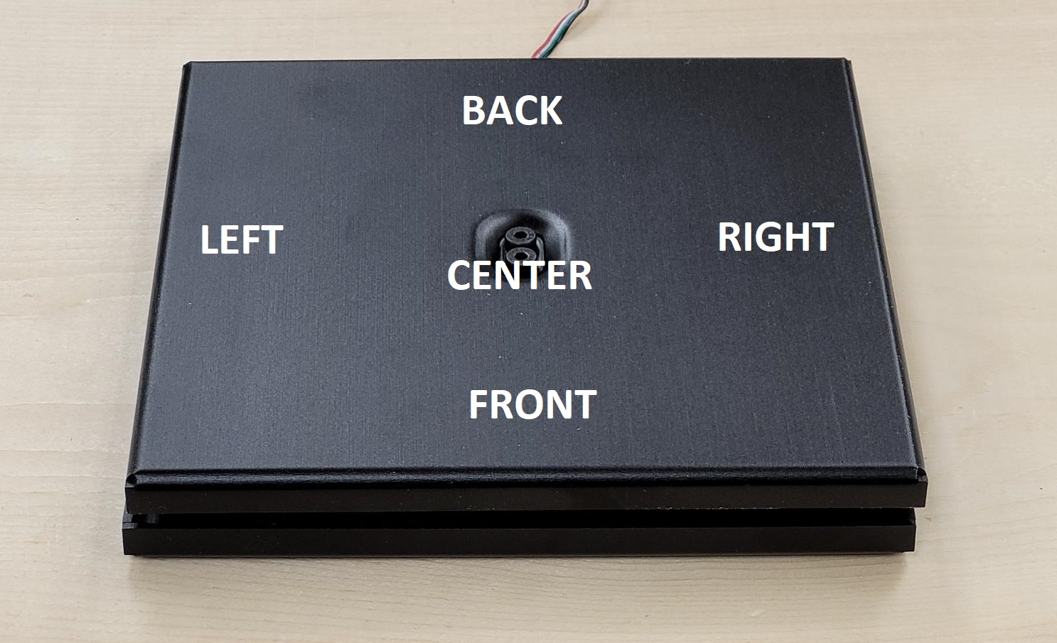
It's worth mentioning there's one scenario where positioning on a scale doesn't matter: when a matched set of platform load cells (like the FRC4140) are used. Because the four load cells are calibrated to the exact same output characteristic, you can wire all four in parallel to a single bridge input and calibrate them as one load cell without worrying about positioning.
Longer Timeframes
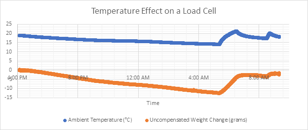
Things get a bit more interesting if you want to run a load cell over longer periods of time. Load cells are sensitive to temperature to a degree that varies from load cell to load cell, depending on the size, manufacturing tolerances, and strain gauge quality. Even changes to room temperature throughout the day can have a visible effect on the measurements from the sensor. (Fig2)
We performed a test between four load cells of differing accuracy grades: One consumer-grade load cell (3134_0), one C2 load cell (FRC4122_0), one C3 load cell (FRC4129_0), and one C4 load cell (FRC4127_0). When subjected to changing temperatures within their rated range (-10 to +40°C), you can see the corresponding change in output voltage. (Fig3)
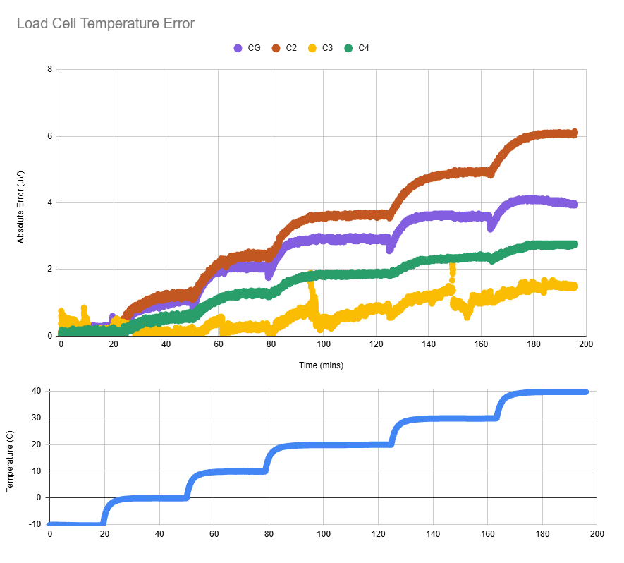
From these results, we can see that while load cell accuracy grade indicates better accuracy and lower error, it does not necessaraily provide better temperature immunity. Since this test spans a full 200 minutes, the error shown here is actually temperature dependence plus drift. While this may look bad, even in the worst case, 6 microvolts is not a huge amount. For a 20kg load cell, 6uV would be equivalent to ~24g. For many applications, drift may be a larger concern. If you still wish to correct for temperature, we'll walk through the process now.
For the simplest temperature compensation calculation, choose two points in the data you collect (preferably separated by the largest difference in temperature) and divide the change in load cell V/V by the change in temperature. You now have the load cell’s temperature compensation coefficient (we’ll call it Mtemp).
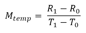
- R0 and R1 are the readings from the load cell, in the case of the DAQ1500 these will be in V/V
- T0 and T1 are the temperatures that the readings R0 and R1 were taken at, respectively.
Any time you use the scale, you can read the temperature of the load cell and multiply the difference in temperature from your temperature reference, and add the result to your load cell’s measurement.

- T0 is the temperature at which you last zeroed your load cell
- T is the current temperature
- R is the current reading from the load cell
- Rcomp is the temperature compensated reading from the load cell
To apply temperature compensation and load cell calibration all in one step we get:

- Fmeas is the actual force measured by the load cell
- Mcal is the calibration gain to convert raw measurements to a real value
- R0 is the sensor’s offset
- T0 is the temperature of the sensor when it was zeroed
This all seems easy enough, just put a temperature sensor beside your weigh-scale and be off to the races, right?
Not quite.
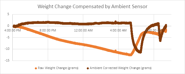
From Fig4, we can see the ambient temperature sensor works quite well to counter the temperature effect during periods of slow temperature change, but the correction falls apart with faster changes (such as when the heater kicks in for the morning). When the temperature of the room changes quickly, the ambient temperature sensor will track the temperature of the air much more closely than the much heavier weigh-scale. The resulting effect is that temperature compensating against an ambient temperature sensor can lose track of the temperature of the load cell itself, resulting in similarly bad (and arguably worse) results.
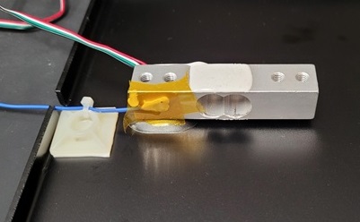
So what options do we have for tracking the load cell directly? For easy use with Phidgets, there are two main options: thermocouples and RTDs. Both of these sensors can have probes in small enough form factors to be pasted directly onto the load cell itself, but we recommend using RTDs for best accuracy and reliability. We used Kapton tape with a blob of thermal paste with an unshielded RTD. Be sure to attach your temperature probe on the static (not moving) side of the load cell.
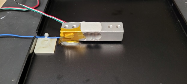
By directly probing the temperature of the load cell, the temperature correction more closely follows the temperature of the sensing components, allowing temperature effects to be all-but eliminated.
Load Cell Self-Heating?
Due to the construction of load cells as effectively a set of resistors, it is easy to imagine these sensors could have a problem with self-heating if left on for enough time. However, through the course of collecting data for this article, we can safely conclude that any self-heating effects are dwarfed by changes in room temperature.
In more certain terms: self-heating is not a large contributor to load cell drift over time.
Conclusions
If you are planning to use your load-cell for periods ranging from a few seconds to 5 minutes at a time between zeroing the scale, the load cell will have very predictable and repeatable results regardless of the load cell's accuracy grade. If you plan to run your load cells for longer periods of time, especially in environments that will see significant temperature variation, we recommend choosing a larger, higher-quality load cell with less temperature dependence. If size is a constraint and you need to use a small load cell, you may want to use a small RTD or thermocouple to measure the temperature of the load cell directly for temperature compensation. This will ensure consistent results without the need to re-zero the load cell as the temperature changes.