Digital Output Guide
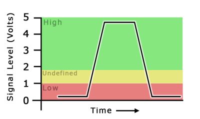
A digital signal is either high or low (1 or 0). Digital output devices can generate a high or low signal, which drives other electronics. Read this guide for more information.


Note: The 1019_1B is identical to the 1019_1, except that you have the option of whether you want to include the USB cable.
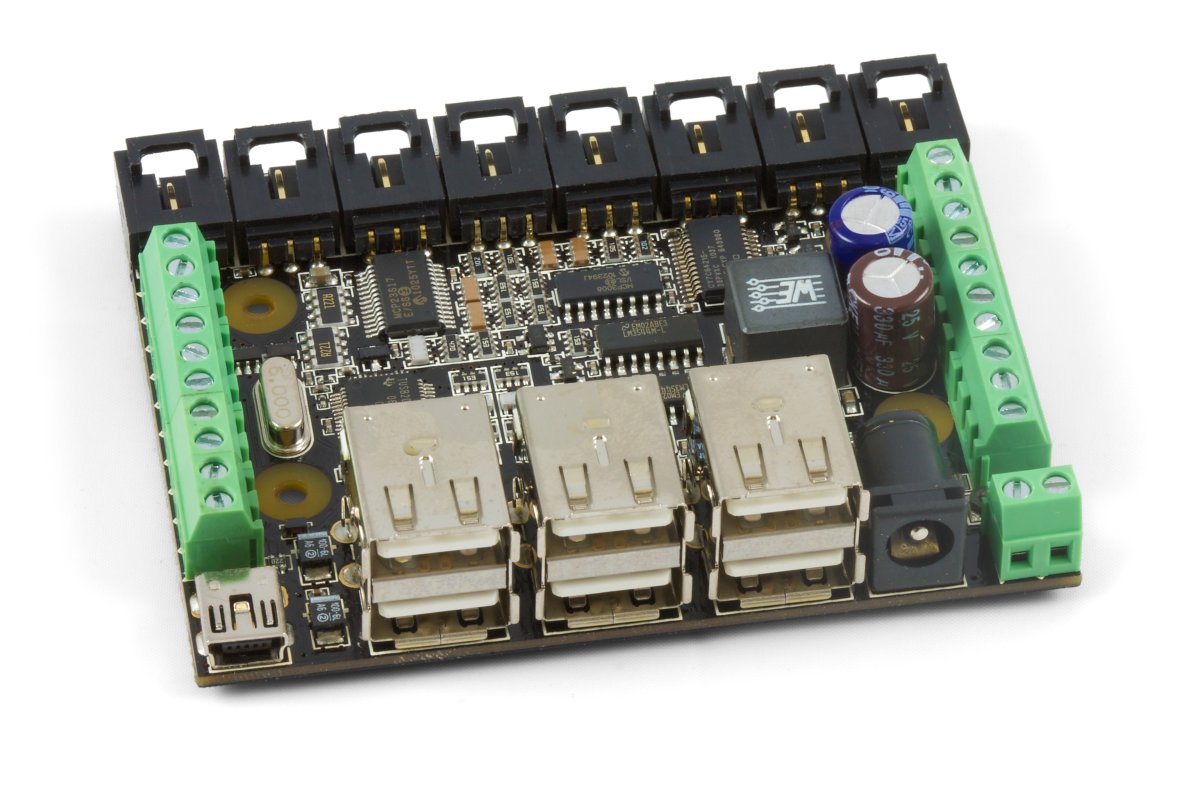
The PhidgetInterfaceKit 8/8/8 puts you in control of 8 analog inputs, 8 digital inputs, and 8 digital outputs.
The analog inputs are used to measure continuous voltage outputs generated by various sensors such as temperature, humidity, position, or pressure. Phidgets offers a wide variety of sensors that can be plugged directly into the board using the cable included with the sensor.
The Digital Inputs have a Digital Input Hardware Filter to eliminate false triggering from electrical noise. They can be used to convey the state of devices such as push buttons, limit switches, relays, and logic levels.
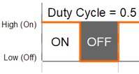
The Digital Outputs can be used to drive LEDs, solid state relays, transistors; in fact, anything that will accept a CMOS signal.
Connecting additional USB devices to the 1019 is as easy as plugging them into the on-board 6-port hub. Each USB port on the hub has a maximum current supply of 500mA.
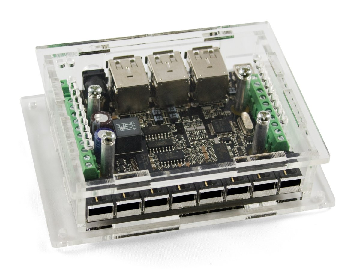
You can protect your board from dust and debris by purchasing an enclosure. An enclosure will also prevent unintentional shorts caused by objects touching the pins on the bottom of the board or any terminal screws.
| Product | Physical Properties | |
|---|---|---|
| Part Number | Price | Material |
 Acrylic Enclosure for the 1019
|
$10.00 | Clear Acrylic |
Use a USB cable to connect this Phidget to your computer. We have a number of different lengths available, although the maximum length of a USB cable is 5 meters due to limitations in the timing protocol. For longer distances, we recommend that you use a Single Board Computer to control the Phidget remotely.
| Product | Physical Properties | |||
|---|---|---|---|---|
| Part Number | Price | Connector A | Connector B | Cable Length |
 USB-A to Mini-B Cable 28cm 24AWG
|
$3.00 | USB Type A | USB Mini-B | 280 mm |
 USB-A to Mini-B Cable 28cm Right Angle
|
$3.50 | USB Type A | USB Mini-B (90 degree) | 280 mm |
 USB-A to Mini-B Cable 60cm 24AWG
|
$3.50 | USB Type A | USB Mini-B | 600 mm |
 USB-C to Mini-B Cable 60cm 28AWG
|
$5.00 | USB Type C | USB Mini-B | 600 mm |
 USB-A to Mini-B Cable 83cm Right Angle
|
$4.50 | USB Type A | USB Mini-B (90 degree) | 830 mm |
 USB-A to Mini-B Cable 120cm 24AWG
|
$4.00 | USB Type A | USB Mini-B | 1.2 m |
 USB-A to Mini-B Cable 180cm 24AWG
|
$4.00 | USB Type A | USB Mini-B | 1.8 m |
 USB-C to Mini-B Cable 180cm 28AWG
|
$6.00 | USB Type C | USB Mini-B | 1.8 m |
 USB-A to Mini-B Cable 450cm 20AWG
|
$12.00 | USB Type A | USB Mini-B | 4.5 m |
To connect analog sensors you'll need Phidget cables. You can solder multiple cables together in order to make even longer Phidget cables, but you should be aware of the effects of having long wires in your system.
| Product | Physical Properties | |
|---|---|---|
| Part Number | Price | Cable Length |
 Phidget Cable 10cm
|
$1.50 | 100 mm |
 Phidget Cable 30cm
|
$1.75 | 300 mm |
 Phidget Cable 60cm
|
$2.00 | 600 mm |
 Phidget Cable 90cm
|
$2.00 | 900 mm |
 Phidget Cable 120cm
|
$2.25 | 1.2 m |
 Phidget Cable 150cm
|
$2.50 | 1.5 m |
 Phidget Cable 180cm
|
$2.75 | 1.8 m |
 Phidget Cable 350cm
|
$3.00 | 3.5 m |
 Phidget Cable Kit
|
$10.00 | 80 mm |
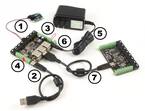
Welcome to the 1019 user guide! In order to get started, make sure you have the following hardware on hand:
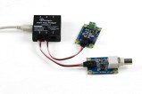
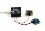
Next, you will need to connect the pieces:
Now that you have everything together, let's start using the 1019!
In order to demonstrate the functionality of the 1019, the Phidget Control Panel running on a Windows machine will be used.
The Phidget Control Panel is available for use on both macOS and Windows machines.
To open the Phidget Control Panel on Windows, find the ![]() icon in the taskbar. If it is not there, open up the start menu and search for Phidget Control Panel
icon in the taskbar. If it is not there, open up the start menu and search for Phidget Control Panel
To open the Phidget Control Panel on macOS, open Finder and navigate to the Phidget Control Panel in the Applications list. Double click on the ![]() icon to bring up the Phidget Control Panel.
icon to bring up the Phidget Control Panel.
For more information, take a look at the getting started guide for your operating system:
Linux users can follow the getting started with Linux guide and continue reading here for more information about the 1019.
After plugging the 1019 into your computer and opening the Phidget Control Panel, you will see something like this:
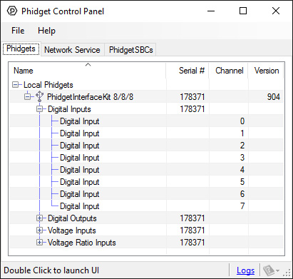
The Phidget Control Panel will list all connected Phidgets and associated objects, as well as the following information:
The Phidget Control Panel can also be used to test your device. Double-clicking on an object will open an example.
Double-click on a Voltage Input object in order to run the example:
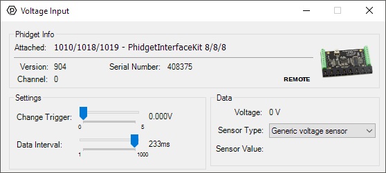
General information about the selected object will be displayed at the top of the window. You can also experiment with the following functionality:
For more information about Voltage Inputs, check out the Voltage Input Primer.
Double-click on a Voltage Ratio Input object in order to run the example:
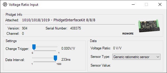
General information about the selected object will be displayed at the top of the window. You can also experiment with the following functionality:
For more information about Voltage Ratio Inputs, check out the Voltage Ratio Input Primer.
Double-click on a Digital Input object in order to run the example:
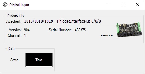
General information about the selected object will be displayed at the top of the window. You can also experiment with the following functionality:
For more information about Digital Inputs, take a look at the Digital Input Primer
Double-click on a Digital Output object in order to run the example:
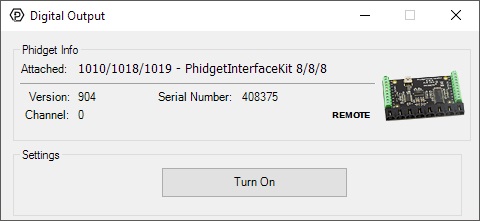
General information about the selected object will be displayed at the top of the window. You can also experiment with the following functionality:
Before you can access the device in your own code, and from our examples, you'll need to take note of the addressing parameters for your Phidget. These will indicate how the Phidget is physically connected to your application. For simplicity, these parameters can be found by clicking the button at the top of the Control Panel example for that Phidget.

In the Addressing Information window, the section above the line displays information you will need to connect to your Phidget from any application. In particular, note the Channel Class field as this will be the API you will need to use with your Phidget, and the type of example you should use to get started with it. The section below the line provides information about the network the Phidget is connected on if it is attached remotely. Keep track of these parameters moving forward, as you will need them once you start running our examples or your own code.

You are now ready to start writing your own code for the device. The best way to do that is to start from our Code Samples.
Select your programming language of choice from the drop-down list to get an example for your device. You can use the options provided to further customize the example to best suit your needs.
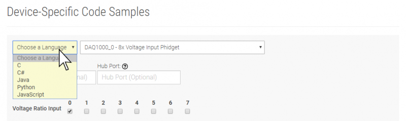
Once you have your example, you will need to follow the instructions on the page for your programming language to get it running. To find these instructions, select your programming language from the Programming Languages page.
The 1019 is not powered from the PC-USB bus. An external 6-15V supply must used to power the 1019 and any attached USB devices. However, the USB hub will not actually be powered until a USB connection is made. The reason for this is that the voltage regulator chip on the 1019 is what routes power to the hub, and it gets its power from the USB line. The 1019 will consume a maximum of 10mA from the USB host cable - allowing it to be directly connected to small hosts that do not provide full USB power.
Connecting additional USB devices to the 1019 is as easy as plugging them into the on-board 6-port hub. Each USB port on the hub has a maximum current supply of 500mA. Ensure the power supply selected has a high enough current output to supply the required current to all external USB devices as well as the 1019 and any sensors or devices connected to it. The worst case requirement is 3 Watts input power per USB device. A 24 Watt 12VDC / 2 Amp power supply would be more than sufficient.
The USB Hub actually has 7 ports, but only 6 of them are used for connecting additional devices since one port is dedicated to the internal 8/8/8 InterfaceKit.
The USB Hub is a full-speed hub with a transfer rate of 12Mbits/second. We chose to go with a full speed implementation since it is fast enough to handle traffic from Phidgets; an added benefit is lower power consumption.
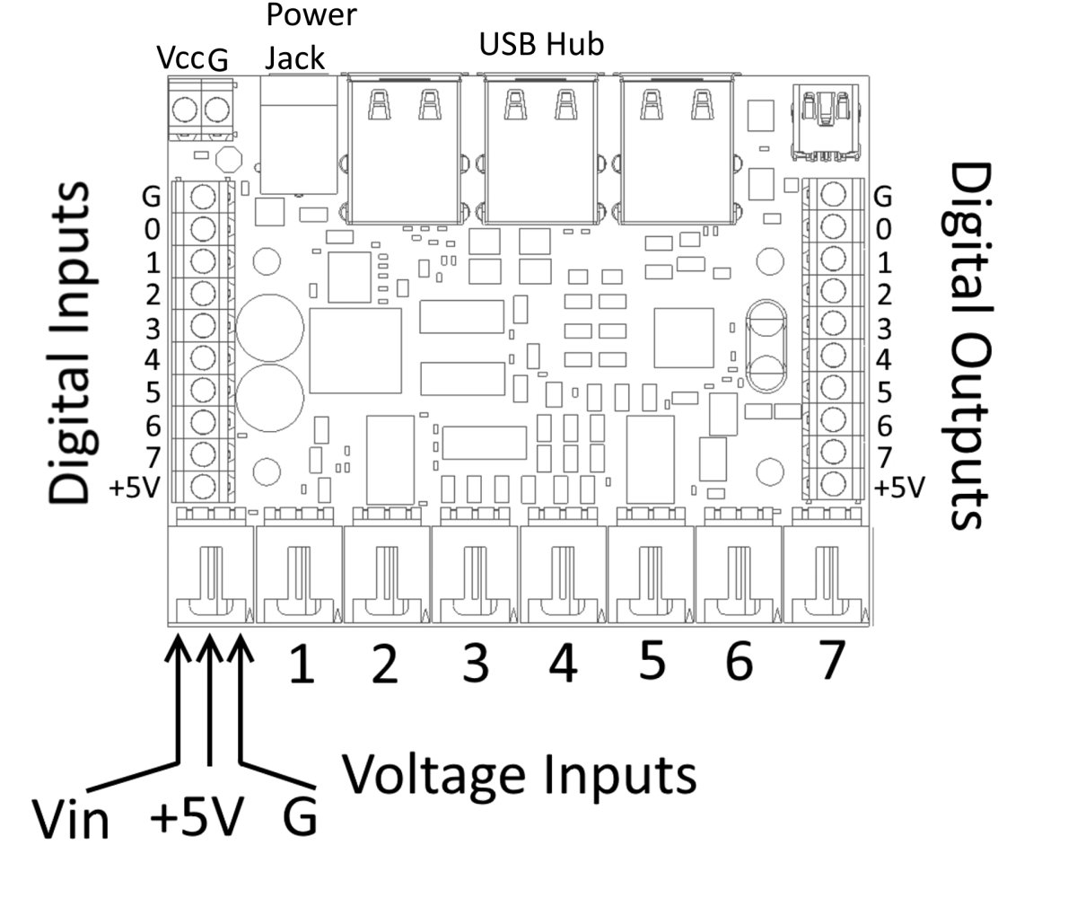
To summarize the power distribution of this board:
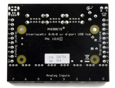
The ports and terminal blocks on this board are labelled on the underside to save space:
The 1019 follows USB specifications and can be daisy chained to the maximum hub depth of 5. A sixth 1019 with a hub plugged into the fifth hub will not be usable at all because the 1019 portion is connected after the hub. However, other Phidgets plugged into the fifth hub will operate normally.
If you want to know more about the input/output capabilities of the 1019 InterfaceKit, check the Digital Input Guide, InterfaceKit Digital Outputs page, and the Analog Input Guide.
| Board Properties | |
|---|---|
| Controlled By | USB (Mini-USB) |
| API Object Name | DigitalInput, DigitalOutput, VoltageInput, VoltageRatioInput |
| USB Voltage Min | 4.6 V DC |
| USB Voltage Max | 5.5 V DC |
| Supply Voltage Min | 6 V DC |
| Supply Voltage Max | 15 V DC |
| Current Consumption Min | 10 mA |
| Current Consumption Max | 500 mA |
| Available External Current | 500 mA |
| Power Jack Hole Diameter | 5.5 mm |
| Power Jack Pin Diameter | 2.1 mm |
| Power Jack Polarity | Center Positive |
| Recommended Wire Size | 16 - 26 AWG |
| USB Speed | Full Speed |
| Operating Temperature Min | 0 °C |
| Operating Temperature Max | 70 °C |
| Voltage Inputs | |
| Number of Voltage Inputs | 8 |
| Voltage Input Resolution (bits) | 10 bit |
| Input Impedance | 900 kΩ |
| Input Voltage Min (DC) | 0 V DC |
| Input Voltage Max (DC) | 5 V DC |
| 5V Reference Error Max | 0.5 % |
| Voltage Input Update Rate Min | 1 samples/s |
| Voltage Input Update Rate Max (4 Channels) | 1000 samples/s |
| Voltage Input Update Rate Max (8 Channels) | 500 samples/s |
| Voltage Input Update Rate Max (WebService) | 62.5 samples/s |
| Digital Inputs | |
| Number of Digital Inputs | 8 |
| Pull-up Resistance | 15 kΩ |
| Low Voltage Max (True) | 900 mV DC |
| High Voltage Min (False) | 4.2 V DC |
| Low Voltage Trigger Length Min | 4 ms |
| High Voltage Trigger Length Min | 15 ms |
| Digital Input Voltage Max | ± 15 V DC |
| Digital Input Update Rate | 125 samples/s |
| Digital Outputs | |
| Number of Digital Outputs | 8 |
| Series Resistance | 300 Ω |
| Digital Output Current Max | 16 mA |
| Digital Output Voltage Min | 0 V DC |
| Digital Output Voltage Max | 5 V DC |
| USB Hub | |
| Number of USB Ports | 6 |
| Available Current per USB Port | 500 mA |
| Customs Information | |
| Canadian HS Export Code | 8471.80.00 |
| American HTS Import Code | 8471.80.40.00 |
| Country of Origin | CN (China) |
| Date | Board Revision | Device Version | Packaging Revision | Comment |
|---|---|---|---|---|
| January 2009 | 0 | 826 | Product Release | |
| November 2011 | 1 | 903 | Replace USB connector with Mini-USB connector. Configurable data sampling speed. Smaller PCB size. | |
| November 2011 | 1 | 904 | getLabelString fixed for labels longer than 7 characters. | |
| January 2018 | 1 | 904 | B | Removed USB cable from packaging |
| Channel Name | API | Channel |
|---|---|---|
| Voltage Input | VoltageInput | 0 - 7 |
| Voltage Ratio Input | VoltageRatioInput | 0 - 7 |
| Digital Input | DigitalInput | 0 - 7 |
| Digital Output | DigitalOutput | 0 - 7 |
| API | Detail | Language | OS | |
|---|---|---|---|---|
| VoltageInput | Visual Studio GUI | C# | Windows | Download |
| VoltageInput | Multi-Channel Example | JavaScript | Browser | Download |
| VoltageInput | JavaScript | Browser | Download | |
| VoltageInput | Objective-C | macOS | Download | |
| VoltageInput | Swift | macOS | Download | |
| VoltageInput | Swift | iOS | Download | |
| VoltageInput | Visual Basic .NET | Windows | Download | |
| VoltageInput | Max/MSP | Multiple | Download | |
| VoltageRatioInput | Visual Studio GUI | C# | Windows | Download |
| VoltageRatioInput | Load Cell Calibrator | C# | Windows | Download |
| VoltageRatioInput | JavaScript | Browser | Download | |
| VoltageRatioInput | Objective-C | macOS | Download | |
| VoltageRatioInput | Swift | macOS | Download | |
| VoltageRatioInput | Swift | iOS | Download | |
| VoltageRatioInput | Visual Basic .NET | Windows | Download | |
| VoltageRatioInput | Max/MSP | Multiple | Download | |
| DigitalInput | Visual Studio GUI | C# | Windows | Download |
| DigitalInput | JavaScript | Browser | Download | |
| DigitalInput | Multi-Channel Example | JavaScript | Browser | Download |
| DigitalInput | Objective-C | macOS | Download | |
| DigitalInput | Swift | macOS | Download | |
| DigitalInput | Swift | iOS | Download | |
| DigitalInput | Visual Basic .NET | Windows | Download | |
| DigitalInput | Max/MSP | Multiple | Download | |
| DigitalOutput | Visual Studio GUI | C# | Windows | Download |
| DigitalOutput | JavaScript | Browser | Download | |
| DigitalOutput | Multi-Channel Example | JavaScript | Browser | Download |
| DigitalOutput | Objective-C | macOS | Download | |
| DigitalOutput | Swift | macOS | Download | |
| DigitalOutput | Swift | iOS | Download | |
| DigitalOutput | Visual Basic .NET | Windows | Download | |
| DigitalOutput | Max/MSP | Multiple | Download |
| Product | Voltage Inputs | Digital Outputs | Digital Inputs | |
|---|---|---|---|---|
| Part Number | Price | Number of Voltage Inputs | Number of Digital Outputs | Number of Digital Inputs |
 PhidgetInterfaceKit 8/8/8
|
$80.00 | 8 | 8 | 8 |
 PhidgetInterfaceKit 2/2/2
|
$50.00 | 2 | 2 | 2 |
 PhidgetInterfaceKit 8/8/8
|
$80.00 | 8 | 8 | 8 |
 PhidgetInterfaceKit 8/8/8 Mini-Format
|
$70.00 | 8 | 8 | 8 |
 PhidgetInterfaceKit 8/8/8 w/6 Port Hub
|
$110.00 | 8 | 8 | 8 |
 PhidgetTextLCD 20X2 : White : Integrated PhidgetInterfaceKit 8/8/8
|
$70.00 | 8 | 8 | 8 |