Voltage Ratio Input Guide
Introduction
Voltage Ratio Input ports are used to measure the ratio between the voltage on the white (data) wire of the Phidget Cable and the 5V source, as a ratio between 0 and 1. It is common for a sensor to output a voltage ratio in order to relay information about what it is measuring. For example, the 1124 temperature sensor and the 1108 magnetic sensor have the following characteristics:

Sensor Voltage Ratio (V/V) |
1124_0 Measured Temperature (°C) |
1108_0 Measured Magnetic Field (G) |
| 0.1 | -38.89 | 400 |
| 0.5 | 49.99 | 0 |
| 0.7 | 94.43 | -200 |
This means that if you want to know the temperature or magnetic field (or pressure, humidity, position, etc.), you will need to measure the sensor's output voltage ratio. In order to do this, you can use any of our Phidgets with an analog input.
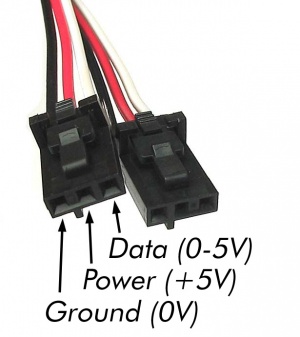
Each Phidget with an analog input interfaces with sensors using three wires:
- Power (+5 VDC) - provides the sensor with power.
- Ground
- Data - The sensor manipulates the voltage on this line. The Phidget measures and reports this voltage.
What is Voltage Ratio?
Ratiometric sensors output a signal as a ratio of the voltage of their power supply. In the case of Phidgets, this power is supplied by the USB port it's plugged into. The 5V power supplied by USB fluctuates over time and from machine to machine, between 4.4-5.25V. As such, simply measuring the voltage on the data wire and assuming the power source is exactly 5V would produce incorrect results. By measuring the data wire using the Phidget port as a VoltageRatioInput, the voltage on the data (white) wire is measured as a ratio of the voltage between USB 5V (the red wire) and ground, as outlined in the following equation:

Technical Details
Factors that can affect Accuracy
- High Output Impedance - Sensors that have a high output impedance will be distorted by the input impedance of the analog input.
If your output impedance is high, it is possible to correct for this distortion to some extent in your software application.
- Voltage Drop - Phidget cables have some resistance, which can cause voltage to drop across particularly long lengths of cable. For ratiometric sensors in particular, this can affect accuracy. Long cables also potentially expose the line to a greater amount of interference from surrounding electronics.
- Intrinsic Error In Sensors - For many sensors, the error is quite predictable by testing it alongside a more accurate sensor, and can be calibrated out in software.
For sensors that output a specific voltage based on their input, look at the Voltage Input Guide
Ground Protection
Ground terminals on the VINT Hub share a common ground with USB ground. Because they are not internally isolated, these terminals will expose the USB ground potential of the PC to which they are connected. Be sure you are completely familiar with any circuit you intend to connect to the VINT port before it is connected. If a reverse voltage or dangerously high voltage is applied to the input or output terminals, damage to the Phidget or the PC may result.
By using the channel as a VoltageInput, the voltage on the line is measured independently of the USB 5V. For a sensor that outputs a voltage ratio, look at the Voltage Input Guide