Products for USB Sensing and Control

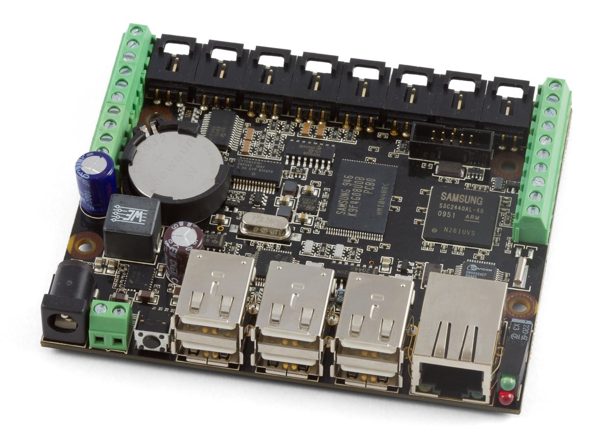
The PhidgetSBC2 is a Single Board Computer with an integrated PhidgetInterfaceKit 8/8/8. At its most basic, it can be thought of as a Phidget that you connect using a network cable instead of USB. The PhidgetSBC2 also provides six full-speed ports that allow you to use normal USB Phidgets over its network connection. This can extend the effective range of a Phidget from USB’s maximum of 15 feet, to anywhere that your network reaches.
The PhidgetSBC2 exposes an easy to use interface for setting up and running custom applications on-board. This allows the PhidgetSBC2 to operate autonomously, without the need for a graphical interface or a remote connection at all times.
For more advanced users, the PhidgetSBC is an embedded computer that runs Debian GNU/Linux. We provide full shell access via a built-in SSH server, access to the full Debian package repository, and all of the standard command line tools expected on a modern Linux system.
An integrated PhidgetInterfaceKit 8/8/8 allows you to connect devices to any of 8 analog inputs, 8 digital inputs and 8 digital outputs. It provides a generic, convenient way to interface your PC and PhidgetSBC with a wide variety of devices and it operates exactly the same way as an external PhidgetInterfaceKit.
When controlling the PhidgetSBC remotely, you can use any Phidgets supported operating systems and languages and you can look at the following code samples that are demonstrating the SBC's PhidgetInterfaceKit functionality.
Support for C, C++, Java, .NET(Mono), or Python can be added from the Debian package repository, as outlined in the product manual.

|
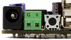
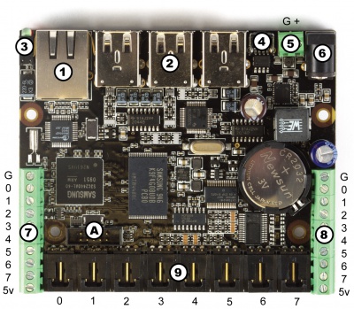
The labeling on the underside of the board for the Power Input Terminal is reversed. The correct polarity is as shown below. |
| SBC | |
|---|---|
| CPU | Samsung S3C2440 |
| Core | ARM920T |
| CPU Speed | 400 MHz |
| NAND Memory Size | 512 MiB |
| SDRAM Size | 64 MiB |
| Boot Time | 30 s |
| Ethernet Cable | 10/100BASE-T |
| Operating System | Debian Linux |
| Board Properties | |
| Supply Voltage Min | 6 V DC |
| Supply Voltage Max | 15 V DC |
| Available External Current | 500 mA |
| Power Jack Hole Diameter | 5.5 mm |
| Power Jack Pin Diameter | 2.1 mm |
| Power Jack Polarity | Center Positive |
| Recommended Wire Size | 16 - 26 AWG |
| Operating Temperature Min | 0 °C |
| Operating Temperature Max | 70 °C |
| Power Consumption Base (w/ Ethernet) | 1.2 W |
| Voltage Inputs | |
| Number of Analog Inputs | 8 |
| Voltage Input Resolution (bits) | 10 bit |
| Input Impedance | 900 kΩ |
| Input Voltage Min | 0 V DC |
| Input Voltage Max | 5 V DC |
| 5V Reference Error Max | 0.5 % |
| Voltage Input Update Rate Min | 1 samples/s |
| Voltage Input Update Rate Max (4 Channels) | 1000 samples/s |
| Voltage Input Update Rate Max (8 Channels) | 500 samples/s |
| Voltage Input Update Rate Max (WebService) | 62.5 samples/s |
| Digital Inputs | |
| Number of Digital Inputs | 8 |
| Pull-up Resistance | 15 kΩ |
| Low Voltage Max (True) | 900 mV DC |
| High Voltage Min (False) | 4.2 V DC |
| Low Voltage Trigger Length Min | 4 ms |
| High Voltage Trigger Length Min | 15 ms |
| Digital Input Voltage Max | ± 15 V DC |
| Digital Input Update Rate | 125 samples/s |
| Digital Outputs | |
| Number of Digital Outputs | 8 |
| Series Resistance | 300 Ω |
| Digital Output Current Max | 16 mA |
| Digital Output Voltage Min | 0 V DC |
| Digital Output Voltage Max | 5 V DC |
| USB Hub | |
| Number of USB Ports | 6 |
| Available Current per USB Port | 500 mA |
| USB Speed | Full Speed |
| Customs Information | |
| Canadian HS Export Code | 8471.80.00 |
| American HTS Import Code | 8471.80.40.00 |
| Country of Origin | CN (China) |
You can protect your board by purchasing the 3817 - Acrylic Enclosure for the SBC.
| Date | Board Revision | Device Version | Comment |
|---|---|---|---|
| February 2011 | 0 | 200 | Product Release |
| Jan 2012 | 0 | 201 | Fixed USB bug |
| March 2012 | 0 | 202 | Changes to recovery system - fix SSH access, fix filename matching to match website files |
| February 2014 | Product Discontinued. Succeeded by the 1073 - PhidgetSBC3. | ||
Make sure you have the latest version of the Phidget Drivers installed on your PC. If you don't, follow these steps:
Double clicking on the ![]() icon will start the Phidget Control Panel, which acts as an easy example launcher and will automatically detect any Phidgets plugged in to your computer. We'll use the Control Panel to ensure that the new Phidget works properly.
icon will start the Phidget Control Panel, which acts as an easy example launcher and will automatically detect any Phidgets plugged in to your computer. We'll use the Control Panel to ensure that the new Phidget works properly.
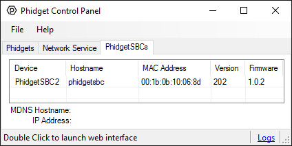
After double clicking on the icon, a window will open with a list of all attached Phidgets. Click on the PhidgetSBC tab, and you should see a list of PhidgetSBCs connected to your network. Double click on an SBC to bring up the configuration page in your default web browser. You can differentiate multiple SBCs by their MAC address, which is printed on a sticker on the underside of the board.
This control panel view will tell you (at the bottom):
You will need one of these two pieces of information when you start working directly with the SBC Operating System for tasks such as writing and running code on the SBC, so write these down somewhere while you work through the rest of this page.
Basic use of the PhidgetSBC allows the opening of connected Phidgets over the network. Using another Phidget with the PhidgetSBC in this way is almost exactly like using Phidgets over USB, in respect to the API calls and behavior. However, some extra considerations need to be made when working with the Phidget Network service.
Support for opening Phidgets over the network is made possible via the Phidget Network service. This allows a user to write an application in a system and language of their choosing and then operate Phidgets connected to the PhidgetSBC. It is a socket based server that runs on the PhidgetSBC, and allows any attached Phidgets to be seen and opened directly over the network. To use this server go to the "Phidgets->Network Service" tab in the web configuration page and enable it.
Opening and controlling a Phidget over the network is nearly the same as opening one locally. The main differences are:
Opening a Phidget over the network is asynchronous and pervasive, just like opening locally. This means that if a connection to the remote server cannot be established right away, it will keep trying indefinitely, and even survive the server being stopped and started, etc. Instances of the Phidget Network service can be referred to either using hostname (IP Address) and port number, or by Server ID. The advantage of using a Server ID is that it stays consistent compared to IP addresses, and you don’t need to know the Port number. A Network service Server ID is assigned when the Network service is run - which on the PhidgetSBC defaults to ‘phidgetsbc’. In order to use a Server ID, the Bonjour utility also needs to be installed. Refer to the Programming Manual and the API manual for your language for more information about using the Phidget Network service.
Determining reliability needs can become important while opening Phidgets over the network, because the network connection can potentially be interrupted at any time. This can leave the network attached Phidget in an undesirable state. For example - if a motor controller is driving a motor and the connection is lost, there is no way to stop the motor until the connection is re-established. These issues are less important if you are just receiving sensor data from an Interface Kit.
It’s generally a good idea to catch server connect and disconnect and Phidget attach and detach events in order to know the state of the connections. It’s also a good idea to catch error events - this is where network errors will be reported. If reliability is important, you should consider writing a program to run locally on the PhidgetSBC, and communicate with it through the Dictionary interface. This way, if the connection is broken, the local application will notice and be able to take any appropriate actions. See the advanced chapter for more information.
Any Phidgets attached to the PhidgetSBC can be identified using the Status >> Phidgets page in the configuration interface, and should be seen on the network through the Network service. The Phidget Control Panel has a Bonjour tab (under Network Service >> Bonjour) that lists all detected network attached Phidgets. The Phidgets connected to the PhidgetSBC should be seen here and can be opened by double clicking its name in the menu. Network attached Phidgets can also be located programmatically with the Phidget Manager. The Phidget Manager is used with either hostname and port, or server ID, just like with ‘Open’. The manager can also be used to find all Phidgets on any Network service through Bonjour, by specifying a NULL Server ID. See your specific language’s guide for more information about coding with the Phidget Manager.
The steps are very similar to the Windows process described above:
The address in the browser that connects to the SBC is either an IP address (such as 192.168.2.181) or a link local address, (such as phidgetsbc.local, which is the default). Note down the address in the browser, as you will need this information for later if you will be working directly with the SBC to perform tasks such as writing or running code. But for now, with the web interface open, we have a section to walk you through it.
With Linux, you have many setup options, but all involve knowing the IP address or link local address of the SBC after you have plugged it in as described in introductory video. The IP address can be somewhat difficult to obtain, but the default link local address for all new Phidget SBCs is phidgetsbc.local - which is an mDNS address. Wait at least three minutes after booting the SBC to make sure link local addressing is started. You'll also need some form of mDNS (either avahi or mDNSResponder) installed on your main computer. The avahi service is usually installed by default on most Linux machines, try which avahi-resolve to make sure. Then, try typing phidgetsbc.local into a web browser. The web interface should come up, starting with the Set the Password screen.
Note that some browsers (i.e. Google Chrome) combine search and addressing in the same address bar, so you may need to turn off Network service and prediction service in Preferences → Under The Bonnet for Chrome to treat phidgetsbc.local like a web address rather than a search term. If these steps do not bring you to the initial setup password screen as shown in the SBC Web Interface section, you will probably need to read the internet setup section on the SBC OS Page. That section contains more than just troubleshooting information - it includes in-depth information on how the SBC starts its network, your initial network configuration options, and how to connect to the SBC without mDNS using both DHCP and static IP.
If you want to use the SBC to broadcast data from Phidgets over a network, the SBC is already automatically performing this function with its attached Interface Kit, and will also do so for any Phidgets plugged into its USB ports. If this is your sole intended use of the SBC, you can skip ahead to our example on using the attached Interface Kit.
However, the SBC is much, much more than simply a way to get data from Phidgets over a network. You can use the SBC as an external Linux computer. You'll need to set a password using the SBC web interface, and write down a network address of the SBC (phidgetsbc.local, or an IP address if you worked through the internet setup section on the SBC OS Page). But after that, if no other sections in the basic SBC web interface section apply to you (using the webcam, setting up wireless networking, or checking system parameters like memory), you can skip ahead to the OS - Phidget SBC page.
As soon as the SBC boots and can connect to the network (either by DHCP or by mDNS/avahi), it begins broadcasting the state of its attached InterfaceKit over the network using the Phidget Network Server. To test the InterfaceKit on your Linux computer over the network, you will need to install the Phidget libraries and the Phidget Network Server if you haven't already. (If you have used any Phidget via USB and over a network on your Linux computer, you have already done this.) This process is described on the general Linux OS page, so follow those installation instructions, with the following modifications to the Linux Network Server introduction:
phidgetsbc) address,openRemoteIP in your code, use the function call openRemote, and the Interface Kit serial number which is on the back of the SBC.Note that any attached analog sensors in the black ports will not show up over the Network Server as individual Phidgets. Rather, they will show up as part of the Interface Kit, through the port number that they are attached to on the SBC board.
To reboot the device, quickly press the black reset button found between the USB connectors and the power terminals. Both Ethernet Port LEDs (yellow-connectivity, green-activity), and the green status LED will turn off. The reboot is done when all LEDs come back on in about 25 seconds.
To reset the firmware, press and hold the button for 10 seconds until the green status LED begins to blink, then release. Both Ethernet Port LEDs will turn off (yellow-connectivity, green-activity) for 80 seconds; the green status LED will then turn off; then all LEDs will come back on in 20 seconds. All data will be lost and the operating system will be reset to a factory state.
To boot into the Recovery / Upgrade system, hold the button for 20 seconds until the green status LED switches from blinking slowly to blinking quickly, then release. The recovery system allows for factory reset, full system upgrades and recovery of the main system.
The recovery / upgrade system is a small system from which the main system can be reset/upgraded, or recovered.
The recovery system can be entered in two ways.
Generally, you should not need to do a full system upgrade. Upgrades are meant to be performed via the package system, and Phidgets maintains it’s own package repository from which to push out updates.
Occasionally, you may wish to go back to a clean install and upgrade to the latest rootfs/kernel from Phidgets. Phidgets will not be creating these images with every release of phidget21 as we did with PhidgetSBC1, rather they will be released several times a year, as needed for major changes not easy to push out via packages.
You can also flash your own custom kernel or root filesystem image.
This restores the kernel and root filesystem from backup, overwriting any changes that may have been made. This is equivalent to holding down the reset button for 10 seconds.
If the main filesystem has been damaged/misconfigured in such a way that it won’t boot, you may be able to fix the issue / recovery important files before running a reset. The recovery system runs an SSH server that you can loginto for console access. Username/password is: root/root.
You can mount the main root filesystem with the following commands (assuming it’s not damaged):
|
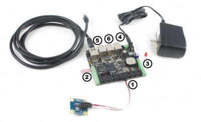
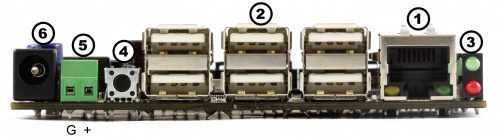
Numbered in the circles on the diagram:
|
| |
The 12V power supply is stepped down to 5V and distributed in the following way:
Power over Ethernet can be used to provide both a network connection and power to a device when a power outlet is not available. This means that with the proper adapters, you can run the PhidgetSBC entirely off an Ethernet source. The PhidgetSBC does not draw power directly from a powered Ethernet line, but instead can use a setup where the power is split to a separate line again near the PhidgetSBC. The board has been tested and will work with Power Sourcing Equipment that can output 6-12VDC.
The PhidgetSBC is based around the SC32440 processor. This is an ARM-920T based microprocessor from Samsung, which runs at 400MHz. Connected to this is 64 MB of SDRAM, 512 MB of large page NAND and a 10/100baseT Ethernet controller. The microprocessor brings USB Host port is connected to a 7-port USB 1.1 Hub chip. The integrated PhidgetInterfaceKit 8/8/8 is connected to one of the hub ports, with the other 6 ports being brought out to the user.
The PhidgetSBC runs Debian/GNU Linux as its operating system and gets booted with U-Boot. The kernel is 2.6.x and generally kept up to date with the latest releases. The root filesystem is created using Buildroot and is mounted in a ~460MB nand partition using the UBIFS filesystem, in Read-Write mode.
Configuration data is located at ‘/etc/webif’. This is where all configuration that can be set through the website is located.
User applications are stored in ‘/usr/userapps’, each is their own directory.
The kernel is stored on bare Nand in it own 3MiB partition, in the uImage format.
The date and time are set using ntp (network time protocol) at boot. The ntp daemon continues to run in the background and will periodically update the clock, keeping it very close to real time.
There is a real-time clock with battery backup which will preserve date/time across reboots, power removal. The real-time clock is synced to system time during reboot/shutdown. If power is unplugged suddenly, the real-time clock may not have the correct time.
Wireless networking is supported using the available adapter and is configured through the configuration interface.
The configuration system used by the website is stored in ‘/etc/webif’. These files should generally not be changed manually, but there is no reason why they could not be. It’s very easy to enter invalid data that could cause the system to behave unexpectedly or not boot.
The board contains 64MB on Nand. This nand is split into 7 partitions as follows:
| 0: u-boot | size: 256K | Read Only |
| 1: u-boot_env | size: 128K | Read Only |
| 2: recovery_kernel | size: 2M | Read Only |
| 3: kernel | size: 3M | Writable |
| 4: flashfs | size: ~3.625M | Read Only |
| 5: recovery_fs | size: ~ 43M | Read Only |
| 6: rootfs | size: ~ 460M | Writable |
The final size of flashfs/recovery_fs/rootfs depends on the image size at production, and on the number/location of bad blocks in the NAND.
U-Boot and recovery kernel and filesystem cannot be written from Linux - this is a safety measure.
This describes the boot process from power on.
The SBC kernel contains driver support for the following USB to Serial Adapters. Please consult the kernel documentation for details into the driver support for the USB to Serial adapters.
| Company | Product |
|---|---|
| ConnectTech | WhiteHEAT |
| Keyspan | USA-18X, USA-28, USA-28X, USA-28XA, USA-28XB, USA-19, USA-19W, USA-19QW, USA-19QI, USA-49W, USA-49WLC |
| FTDI | Single Port Serial Adapter |
| Cypress | M8 CY4601 Family |
| Digi International | AccelePort USB Serial |
| Belkin | USB Serial Adapter F5U103 |
| MCT | USB Single Port Serial Adapter U232 |
| Inside Out Networks | Edgeport Serial Adapter |
| Prolific | PL2303 |
U-Boot is used for setting up the processor and booting Linux, and is only accessible by the serial port. Normal users will not need to use it. If you are connected to the serial port, you will see the U-Boot prompt shortly after power up. You can view the environment variables for information on how to properly boot Linux on the PhidgetSBC.
Be very careful when modifying the u-boot partition. If it is damaged or overwritten, it is difficult to fix.
Refer to U-Boot documentation here: www.denix.de/wiki/DULG/Manual for more information on using U-Boot.
The SBC can be configured as a device in an ad-hoc network.
For more information, visit the Ad-Hoc Networks page.
There is a known issue with the USB Hub on 1072s manufactured before 2012. You can read the article on how to fix it here.
Check the Phidget SBC page for more details about using the Phidget SBC.
Check the 1018 User Guide for more information about the InterfaceKit on this board.
| Channel Name | API | Channel |
|---|---|---|
| Voltage Input | VoltageInput | 0 - 7 |
| Voltage Ratio Input | VoltageRatioInput | 0 - 7 |
| Digital Input | DigitalInput | 0 - 7 |
| Digital Output | DigitalOutput | 0 - 7 |