TMP1101 User Guide: Difference between revisions
No edit summary |
No edit summary |
||
| Line 1: | Line 1: | ||
__NOINDEX__ | __NOINDEX__ | ||
__NOTOC__ | |||
<metadesc>Connect up to four K, J, E or T type thermocouples to the 4x Thermocouple Phidget to measure the temperature of the air or an object.</metadesc> | <metadesc>Connect up to four K, J, E or T type thermocouples to the 4x Thermocouple Phidget to measure the temperature of the air or an object.</metadesc> | ||
[[Category:UserGuide]] | [[Category:UserGuide]] | ||
== | ==Part 1: Setup== | ||
{{UGIntro|TMP1101}} | {{UGIntro|TMP1101}} | ||
* [{{SERVER}}/products.php?product_id=TMP1101 TMP1101 - 4x Thermocouple Phidget] | * [{{SERVER}}/products.php?product_id=TMP1101 TMP1101 - 4x Thermocouple Phidget] | ||
| Line 20: | Line 21: | ||
{{UGIntroDone|TMP1101}} | {{UGIntroDone|TMP1101}} | ||
{{UGcontrolpanel|TMP1101}} | {{UGcontrolpanel|TMP1101}} | ||
== Part 2: Using Your Phidget == | |||
===About=== | |||
The TMP1100 allows you to measure extreme temperatures with up to 4 thermocouples. This Phidget connects to a J, K, E, or T type thermocouple. Choose the thermocouple type in software and data will be converted to degrees Celsius automatically. If you have other thermocouple types, you can open the channel in VoltageInput mode and convert it to Celsius manually. | |||
===Explore Your Phidget Channels Using The Control Panel=== | |||
You can use your Control Panel to explore your Phidget's channels. | |||
'''1.''' Open your Control Panel, and you will find the following channels: | |||
== | [[Image:TMP1101_Panel.jpg|link=|center]] | ||
{{ | |||
'''2.''' Double click on a channel to open an example program. | |||
{{UGC-Start}} | |||
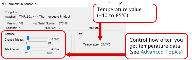
{{UGC-Entry|Temperature Sensor (IC):| Measures the ambient temperature| | |||
In your Control Panel, double click on "Temperature Sensor (IC)": | |||
[[Image:TMP1101-TemperatureSensorIC.jpg|center|link=]]}} | |||
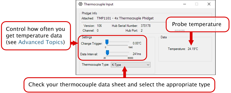
{{UGC-Entry|Thermocouple Input:| Reports the probe temperature| | |||
In your Control Panel, double click on "Thermocouple Input": | |||
[[Image:TMP1101-TemperatureSensorTC.jpg|center|link=]]}} | |||
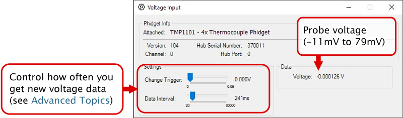
{{UGC-Entry|Voltage Input:| Measures the raw probe voltage| | |||
In your Control Panel, double click on "Voltage Input": | |||
[[Image:TMP1101-VoltageInput.jpg|center|link=]]}} | |||
{{UGC-End}} | |||
{{UG-Part3}} | |||
== Part 4: Advanced Topics and Troubleshooting == | |||
{{UGC-Start}} | |||
{{UGC-Addressing}} | |||
{{UGC-DataInterval}} | |||
{{UGC-Entry|Cold Junction Compensation and Self-heating|| | |||
Thermocouples consist of two junctions, one where the thermocouple meets the Phidget and one where the two wires are welded together at the sensing end of the device. In simplified terms, a thermocouple works by detecting the temperature difference between these two junctions. To measure the temperature at the sensing end we need to know the temperature where the thermocouple connects to the Phidget. There is an ambient temperature sensor on the board. The thermocouple reading is automatically calculated using the data from the on board temperature sensor. | |||
An important thing to note is that the ambient temperature sensor measures the temperature of the board and the air around it, though not specifically at the junction. Generally you can assume they are nearly the same temperature, however as the electronics heat up by being powered on there can be some small error introduced. This is exacerbated by having the board in an enclosed space where normal airflow is restricted thereby increasing the effect of self-heating. As a result we recommend that the board be left in as open and well ventilated/cooled a place as possible to minimize this error source. | |||
For more information on thermocouples, check out the [[Thermocouple Primer]]. | For more information on thermocouples, check out the [[Thermocouple Primer]]. | ||
}} | |||
{{UGC-Entry|50Hz/60Hz Filtering|| | |||
One of the most common sources of electrical noise in a system is 50Hz or 60Hz hum from the local power grid. For firmware versions 107 and later for this Phidget, we have added a filter to compensate for 50Hz or 60Hz hum in your system. | |||
Without filtering, sensors in electrically noisy environments could see a repeating drift of tens of degrees, as noise from power lines finds its way into the system. The timing of this drift could vary, depending on how the samples from the sensor lined up with the noise from the power lines. | |||
To combat this issue, all thermocouple temperature and voltage measurements on this device are now passed through a 100ms moving average filter, with samples taken at specific intervals designed to cancel out frequencies of 50Hz and 60Hz (the most common power grid frequencies). The filtering on this Phidget will reduce the effect of power line noise by 95% or more, becoming more effective as the power line frequency approaches 50Hz or 60Hz exactly. | |||
{{ | All samples from the sensor will be subject to filtering. When used with data intervals longer than 100ms, the sensor will measure the thermocouple(s) for 100ms to perform a measurement. When using data intervals less than 100ms, your application will see the effects of the latest measurements as they pass through the filter. | ||
}} | |||
{{UGC-End}} | |||
Revision as of 21:38, 4 August 2020
Part 1: Setup
Welcome to the TMP1101 user guide! In order to get started, make sure you have the following hardware on hand:
- TMP1101 - 4x Thermocouple Phidget
- VINT Hub
- Phidget cable
- USB cable and computer
- Thermocouple
Next, you will need to connect the pieces:
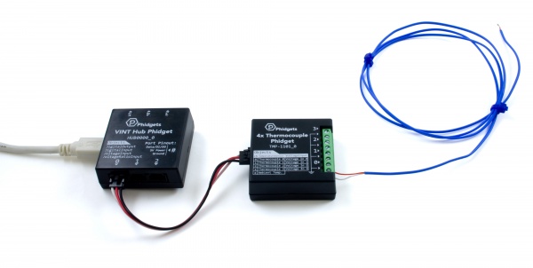
- Connect the thermocouple to one of the inputs on the TMP1101. The datasheet or product page for the thermocouple should tell you which wire is positive and which is negative.
- Connect the TMP1101 to the VINT Hub using the Phidget cable.
- Connect the VINT Hub to your computer with a USB cable.
Now that you have everything together, let's start using the TMP1101!
Phidget Control Panel
In order to demonstrate the functionality of the TMP1101, the Phidget Control Panel running on a Windows machine will be used.
The Phidget Control Panel is available for use on both macOS and Windows machines.
Windows
To open the Phidget Control Panel on Windows, find the ![]() icon in the taskbar. If it is not there, open up the start menu and search for Phidget Control Panel
icon in the taskbar. If it is not there, open up the start menu and search for Phidget Control Panel
macOS
To open the Phidget Control Panel on macOS, open Finder and navigate to the Phidget Control Panel in the Applications list. Double click on the ![]() icon to bring up the Phidget Control Panel.
icon to bring up the Phidget Control Panel.
For more information, take a look at the getting started guide for your operating system:
Linux users can follow the getting started with Linux guide and continue reading here for more information about the TMP1101.
First Look
After plugging the TMP1101 into your computer and opening the Phidget Control Panel, you will see something like this:
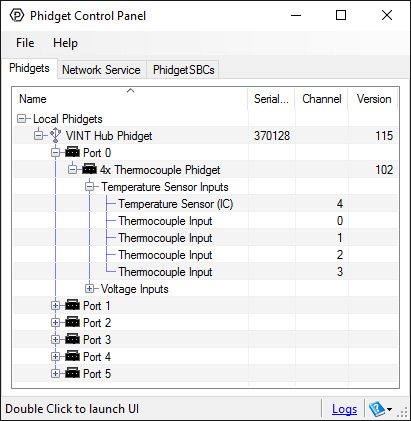
The Phidget Control Panel will list all connected Phidgets and associated objects, as well as the following information:
- Serial number: allows you to differentiate between similar Phidgets.
- Channel: allows you to differentiate between similar objects on a Phidget.
- Version number: corresponds to the firmware version your Phidget is running. If your Phidget is listed in red, your firmware is out of date. Update the firmware by double-clicking the entry.
The Phidget Control Panel can also be used to test your device. Double-clicking on an object will open an example.
Part 2: Using Your Phidget
About
The TMP1100 allows you to measure extreme temperatures with up to 4 thermocouples. This Phidget connects to a J, K, E, or T type thermocouple. Choose the thermocouple type in software and data will be converted to degrees Celsius automatically. If you have other thermocouple types, you can open the channel in VoltageInput mode and convert it to Celsius manually.
Explore Your Phidget Channels Using The Control Panel
You can use your Control Panel to explore your Phidget's channels.
1. Open your Control Panel, and you will find the following channels:
2. Double click on a channel to open an example program.
In your Control Panel, double click on "Temperature Sensor (IC)":
In your Control Panel, double click on "Thermocouple Input":
In your Control Panel, double click on "Voltage Input":
Part 3: Create your Program
1. Setting up your Programming Environment
Part 4: Advanced Topics and Troubleshooting
Before you open a Phidget channel in your program, you can set these properties to specify which channel to open. You can find this information through the Control Panel.
1. Open the Control Panel and double-click on the red map pin icon:

2. The Addressing Information window will open. Here you will find all the information you need to address your Phidget in your program.

See the Phidget22 API for your language to determine exact syntax for each property.
The Change Trigger is the minimum change in the sensor data needed to trigger a new data event.
The Data Interval is the time (in ms) between data events sent out from your Phidget.
The Data Rate is the reciprocal of Data Interval (measured in Hz), and setting it will set the reciprocal value for Data Interval and vice-versa.
You can modify one or both of these values to achieve different data outputs. You can learn more about these properties here.
Thermocouples consist of two junctions, one where the thermocouple meets the Phidget and one where the two wires are welded together at the sensing end of the device. In simplified terms, a thermocouple works by detecting the temperature difference between these two junctions. To measure the temperature at the sensing end we need to know the temperature where the thermocouple connects to the Phidget. There is an ambient temperature sensor on the board. The thermocouple reading is automatically calculated using the data from the on board temperature sensor.
An important thing to note is that the ambient temperature sensor measures the temperature of the board and the air around it, though not specifically at the junction. Generally you can assume they are nearly the same temperature, however as the electronics heat up by being powered on there can be some small error introduced. This is exacerbated by having the board in an enclosed space where normal airflow is restricted thereby increasing the effect of self-heating. As a result we recommend that the board be left in as open and well ventilated/cooled a place as possible to minimize this error source.
For more information on thermocouples, check out the Thermocouple Primer.
One of the most common sources of electrical noise in a system is 50Hz or 60Hz hum from the local power grid. For firmware versions 107 and later for this Phidget, we have added a filter to compensate for 50Hz or 60Hz hum in your system.
Without filtering, sensors in electrically noisy environments could see a repeating drift of tens of degrees, as noise from power lines finds its way into the system. The timing of this drift could vary, depending on how the samples from the sensor lined up with the noise from the power lines.
To combat this issue, all thermocouple temperature and voltage measurements on this device are now passed through a 100ms moving average filter, with samples taken at specific intervals designed to cancel out frequencies of 50Hz and 60Hz (the most common power grid frequencies). The filtering on this Phidget will reduce the effect of power line noise by 95% or more, becoming more effective as the power line frequency approaches 50Hz or 60Hz exactly.
All samples from the sensor will be subject to filtering. When used with data intervals longer than 100ms, the sensor will measure the thermocouple(s) for 100ms to perform a measurement. When using data intervals less than 100ms, your application will see the effects of the latest measurements as they pass through the filter.