HUB5000 User Guide: Difference between revisions
(Created page with "__NOINDEX__ __NOTOC__ <metadesc>The Wireless USB VINT Hub has 6 VINT ports allowing for endless possibilities for USB sensing and control via your local network using Wi-Fi or...") |
No edit summary |
||
| (6 intermediate revisions by 4 users not shown) | |||
| Line 3: | Line 3: | ||
<metadesc>The Wireless USB VINT Hub has 6 VINT ports allowing for endless possibilities for USB sensing and control via your local network using Wi-Fi or ethernet.</metadesc> | <metadesc>The Wireless USB VINT Hub has 6 VINT ports allowing for endless possibilities for USB sensing and control via your local network using Wi-Fi or ethernet.</metadesc> | ||
[[Category:UserGuide]] | [[Category:UserGuide]] | ||
== | ==Part 1: Setup== | ||
Before you get started with plugging in and setting up your Wireless VINT Hub, we recommend downloading our libraries from [[Operating_System_Support|here]]. | Before you get started with plugging in and setting up your Wireless VINT Hub, we recommend downloading our libraries from [[Operating_System_Support|here]]. | ||
| Line 27: | Line 27: | ||
[[Image:HUB5000_Panel2.jpg|link=|center]] | [[Image:HUB5000_Panel2.jpg|link=|center]] | ||
The Phidget Control Panel will list all connected Phidgets and associated objects, as well as the following information: | The Phidget Control Panel will list all connected Phidgets and associated objects, as well as the following information: | ||
| Line 36: | Line 37: | ||
If you haven't already, now would be a good time to [[#Upgrading_the_Firmware|upgrade the firmware]] of the HUB5000. Once you're done with that, use the Phidget Control Panel to test your device. Double-clicking on an object will open an example. | If you haven't already, now would be a good time to [[#Upgrading_the_Firmware|upgrade the firmware]] of the HUB5000. Once you're done with that, use the Phidget Control Panel to test your device. Double-clicking on an object will open an example. | ||
==Using | == Part 2: Using Your Phidget == | ||
===About=== | |||
The Wireless VINT Hub provides a stable wireless interface to connect your devices to your computer over your wi-fi network. The Wireless VINT Hub has 6 ports. Each port can either: | |||
* Connect to a VINT Device | |||
* Read a 0-5V Voltage or ratiometric sensor (connect to Analog Input sensors) | |||
* Act as a digital output (control LEDs, relays, digital circuits, and other simple electronics) | |||
* Act as a digital input (read the state of a switch) | |||
===Explore Your Phidget Channels Using the Control Panel=== | |||
[[ | [[Image:HUB5000-panel.jpg|link=|center]] | ||
The Wireless VINT Hub is a connecting point between your computer and device allowing for simple communication. You can use your Control Panel to view your attached Phidgets. Explore the 5 types of connections bellow: | |||
{{UGC-Start}} | |||
{{UGC-Entry|Intelligent VINT Devices| | |||
| | | | ||
[[ | [[Image:vint-v.jpg|350px|link=]] | ||
VINT Devices like the TMP1101 or DCC1003 are Phidgets that digitally communicate with the VINT Hub. Each device will have unique features, so it is recommended you visit the individual product page for more details. | |||
When attached correctly these Phidgets will appear by name in your Control Panel, with each channel listed below the name. For example, when the HUM1000 is attached you will see: | |||
[[ | [[Image:HUM1000_Panel.jpg|link=|center]] | ||
}} | |||
{{UGC-Entry|Digital Input:| read the state of a switch | |||
| | | | ||
[[Image:vint-di.jpg|350px|link=]] | |||
[[Image:vint- | |||
'''Digital Input''' is one of the VINT Hub’s built-in Channel Classes. Any of the these ports can act as an active-low digital input, making them useful for reading switches and buttons. The above image provides an example of how to wire a switch to be used with the VINT Hub. | |||
If you open '''Digital Input Mode''' in the Control Panel you will be able to see the state of your button/switch. | |||
[[Image:HUB0000-di.jpg|link=]] | |||
}} | |||
{ | {{UGC-Entry| Digital Output:| control LEDs, relays, digital circuits, and other simple electronics | ||
| | |||
| | | | ||
[[Image:vint-do.jpg|350px|link=]] | |||
[[Image: | |||
'''Digital Output''' is one of the VINT Hub’s built-in Channel Classes. Any of these ports can be used as a 3.3V digital output, making them useful for blinking LEDs. The above image demonstrates how to connect your LED to be used with the VINT Hub. | |||
Open '''Digital Output Mode''' in the Control Panel to control the 3.3V output. | |||
[[Image:HUB0000-do.jpg|850px|link=]] | |||
}} | |||
{ | {{UGC-Entry| Voltage Input:| Non-ratiometric Analog sensors and monitoring 5V digital circuits | ||
| | |||
| | | | ||
= | [[Image:vint-vi.jpg|350px|link=]] | ||
'''Voltage Input''' is one of the VINT Hub’s built-in Channel Classes. Any of these ports can be used to read voltage, making them great for reading non-ratiometric sensors and monitoring 5V digital circuits. | |||
Open '''Voltage Input Mode''' in the Control Panel to view your device’s output voltage. | |||
[[Image:HUB0000-vi.jpg|850px|link=]] | |||
}} | |||
{{ | {{UGC-Entry| Voltage Ratio Input:| Analog ratiometric sensors | ||
| | |||
| | | | ||
[[Image:vint-vr.jpg|350px|link=]] | |||
'''Voltage Ratio Input''' is one of the VINT Hub’s built-in Channel Classes. Any of these ports can act as a Voltage Ratio Input comparing the voltage provided to the voltage returned by the device, making it useful for connecting ratiometric sensors. The voltage ratio is reported in Volts per Volt. For example, if the Phidget is providing 5V and the sensor is sending back 2.5V, the ratio will be 0.5V/V. | |||
Open '''Voltage Ratio Input Mode''' in the Control Panel to view your device’s voltage ratio. | |||
[[Image:HUB0000-vr.jpg|850px|link=]] | |||
}} | |||
[[Image: | {{UGC-End}} | ||
{{ | {{UG-Part3}} | ||
== Part 4: Advanced Topics and Troubleshooting == | |||
{{ | {{UGC-Start}} | ||
{{UGC-Addressing}} | |||
{{UGC-DataInterval}} | |||
{{UGC-Entry|Upgrading the Firmware| | |||
{ | |||
| | |||
| | | | ||
You can download the most recent HUB5000 firmware binary here: | You can download the most recent HUB5000 firmware binary here: | ||
* [{{SERVER}}/downloads/phidgetsbc/HUB5000/phidgethub5000.bin HUB5000 Firmware] | * [{{SERVER}}/downloads/phidgetsbc/HUB5000/phidgethub5000.bin HUB5000 Firmware] | ||
To upgrade the firmware, go into the web configuration page as outlined in Part 1 of this User Guide. From there, click on "System", and upload this file by click on "select file" under the "Upgrade Firmware" section. After that, click on "Upgrade and Restart". You'll be instructed to wait a few minutes before logging back into the web interface. | |||
When you log in, you can confirm that the new version has successfully installed by checking to see if the firmware version listed in the "Status" section matches the first three numbers in the firmware file name that you downloaded. You can also check the version in the "Network Phidgets" tab on the Phidget Control Panel.}} | |||
{{UGC-Entry|CE Compliance| | |||
| | |||
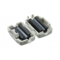
[[Image:ferrite_bead.jpg|link=|200px|right|thumbnail|A clamp-on ferrite bead]] | |||
For an ethernet connected HUB5000 to be completely CE compliant, you must put a ferrite bead on the ethernet cable. Ferrite beads are only necessary when building the HUB5000 into a larger system that needs to be CE compliant. You can find clamp-on ferrite beads at electronic parts stores such as [https://www.digikey.ca/products/en/filters/840 Digikey].}} | |||
{{UGC-Entry|VINT Ports| | |||
| | |||
For more information on the capabilities of the ports on the VINT Hub, see the [[What_is_VINT%3F|VINT Primer]].}} | |||
{{UGC-Entry|Configuration Page| | |||
| | |||
{{hiddenh3|Configuration using the Phidget Control Panel}} | |||
To get to the HUB5000's configuration page, open the Phidget Control Panel and find it under the "Network Phidgets" tab as outlined in Part 1 of this User Guide. | |||
{{hiddenh3|Configuration using Phone}} | |||
If the HUB5000 is in access point mode, you can access the configuration page through your phone: Connect to the HUB5000 Wi-Fi signal and enter the password on the sticker. Once you're connected, go to your internet app and go to address {{code|192.168.100.1}} . This address will take you to the configuration login page. | |||
If the HUB5000 is in access point mode, you can access the configuration page through your phone: Connect to the HUB5000 Wi-Fi signal and enter the password on the sticker. Once you're connected, go to your internet app and go to address {{ | |||
{{hiddenh3|Settings}} | |||
* '''Status:''' This section lists the hardware and firmware version of the HUB5000, along with the network addresses. | * '''Status:''' This section lists the hardware and firmware version of the HUB5000, along with the network addresses. | ||
* '''Network:''' This section allows you to change the network connection settings and switch between Access Point mode and Client mode. | * '''Network:''' This section allows you to change the network connection settings and switch between Access Point mode and Client mode. | ||
* '''Phidgets:''' This section has the Phidget Server controls(including controls to change the log level and view the log file). This section also contains the Web Server controls. | |||
* '''System:''' This section allows you to change the password, and has other advanced settings including firmware upgrade and system/kernel logs.}} | |||
{{UGC-Entry|Factory Reset (Reset Passwords)| | |||
| | |||
[[Image:HUB5000_reset.jpg|link=|300px|right]] | |||
Pressing the reset button will reboot the HUB5000. | |||
Holding the button down for 10 seconds before releasing will perform a reset. The reset will clear all settings, including the web configuration page password, and reset the Wi-Fi password to the one on the HUB5000's label. | |||
As a last resort, you can perform a factory reset. Only perform a factory reset if the regular reset is not working, or there was an error during a firmware upgrade. Holding the button down before plugging in power, and keeping pressed for 15 seconds before releasing, will restore the original factory firmware.}} | |||
{{UGC-Entry|Setting the Device Label| | |||
| | |||
When opening channels with Phidgets, you can set several properties to make sure you are accessing the precise channel you want. The HUB5000 has a unique serial number that can be used to find its ports or any VINT devices connected to them. If you want something more customizable and human-readable, you can use the [[Addressing_Phidgets#Label|device label]] instead. You can customize the device label by using {{code|writeDeviceLabel}} on the {{code|Hub}} object after it has been opened. | |||
When opening channels with Phidgets, you can set | |||
With the device label, you can address any of the VINT Hub's channels, or any connected VINT device channels. The device label will remain after the VINT Hub is unplugged as it is stored in flash memory.}} | |||
{{ | {{UGC-End}} | ||
Revision as of 18:36, 21 April 2020
Part 1: Setup
Before you get started with plugging in and setting up your Wireless VINT Hub, we recommend downloading our libraries from here.
First Look
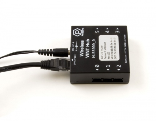
To begin, connect the power supply to the barrel jack on the HUB5000 and connect it to a modem or network switch using an ethernet cable.
After plugging the HUB5000 in, open the Phidget Control Panel and go to the "Network Phidgets" tab. You will see something like this:
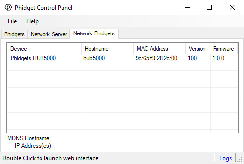
Double click on the HUB5000's row and you'll be brought to a webpage. Select a password and click "submit". You can use this password in the future to access this configuration page.

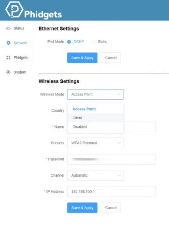
From here, click on the "Network" tab and change the mode from "Access Point" to "Client". You'll have to choose a name and password before saving. If you want to use the HUB5000 wirelessly, you should also enter your Wi-Fi network details here. The HUB5000 should now be accessible from the "Phidgets" tab of the Control Panel.
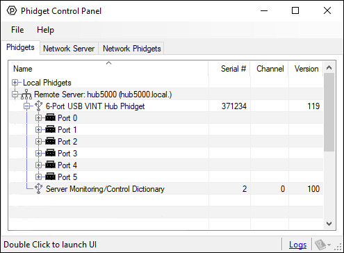
The Phidget Control Panel will list all connected Phidgets and associated objects, as well as the following information:
- Serial number: allows you to differentiate between similar Phidgets.
- Channel: allows you to differentiate between similar objects on a Phidget.
- Version number: corresponds to the firmware version your Phidget is running. If your Phidget is listed in red, your firmware is out of date. Update the firmware by double-clicking the entry.
If you haven't already, now would be a good time to upgrade the firmware of the HUB5000. Once you're done with that, use the Phidget Control Panel to test your device. Double-clicking on an object will open an example.
Part 2: Using Your Phidget
About
The Wireless VINT Hub provides a stable wireless interface to connect your devices to your computer over your wi-fi network. The Wireless VINT Hub has 6 ports. Each port can either:
- Connect to a VINT Device
- Read a 0-5V Voltage or ratiometric sensor (connect to Analog Input sensors)
- Act as a digital output (control LEDs, relays, digital circuits, and other simple electronics)
- Act as a digital input (read the state of a switch)
Explore Your Phidget Channels Using the Control Panel
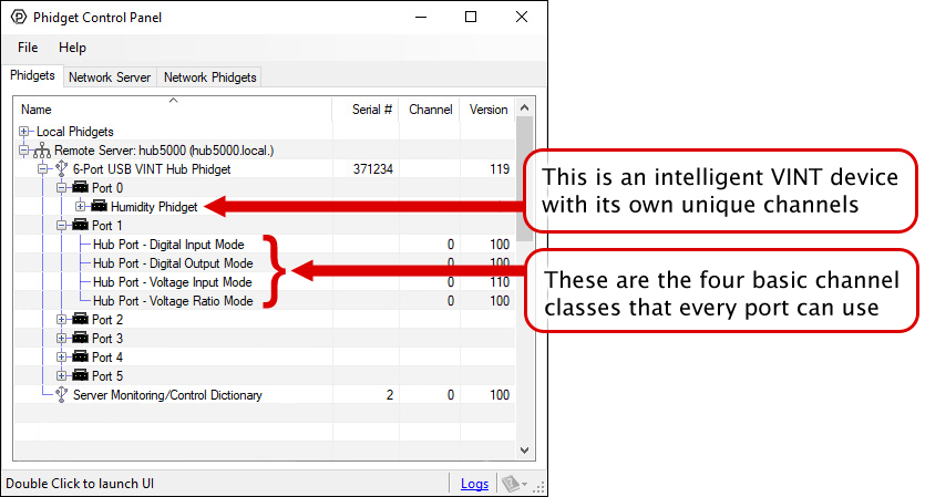
The Wireless VINT Hub is a connecting point between your computer and device allowing for simple communication. You can use your Control Panel to view your attached Phidgets. Explore the 5 types of connections bellow:
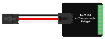
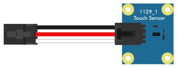
VINT Devices like the TMP1101 or DCC1003 are Phidgets that digitally communicate with the VINT Hub. Each device will have unique features, so it is recommended you visit the individual product page for more details.
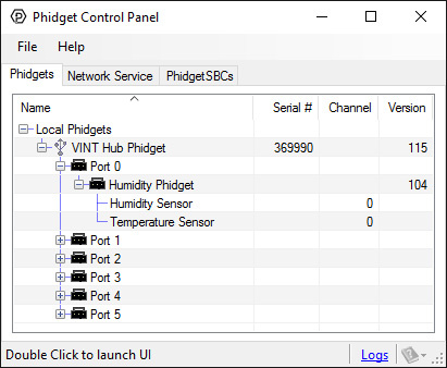
When attached correctly these Phidgets will appear by name in your Control Panel, with each channel listed below the name. For example, when the HUM1000 is attached you will see:
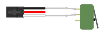
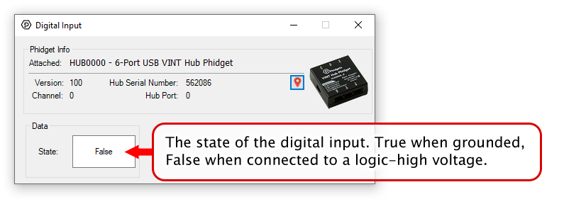
Digital Input is one of the VINT Hub’s built-in Channel Classes. Any of the these ports can act as an active-low digital input, making them useful for reading switches and buttons. The above image provides an example of how to wire a switch to be used with the VINT Hub.
If you open Digital Input Mode in the Control Panel you will be able to see the state of your button/switch.
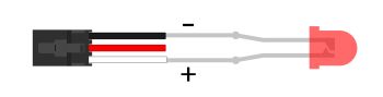
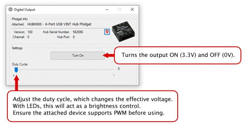
Digital Output is one of the VINT Hub’s built-in Channel Classes. Any of these ports can be used as a 3.3V digital output, making them useful for blinking LEDs. The above image demonstrates how to connect your LED to be used with the VINT Hub.
Open Digital Output Mode in the Control Panel to control the 3.3V output.
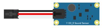
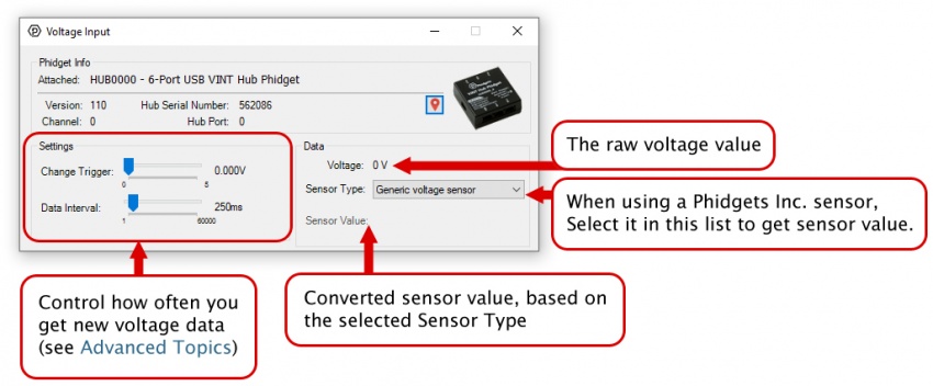
Voltage Input is one of the VINT Hub’s built-in Channel Classes. Any of these ports can be used to read voltage, making them great for reading non-ratiometric sensors and monitoring 5V digital circuits.
Open Voltage Input Mode in the Control Panel to view your device’s output voltage.
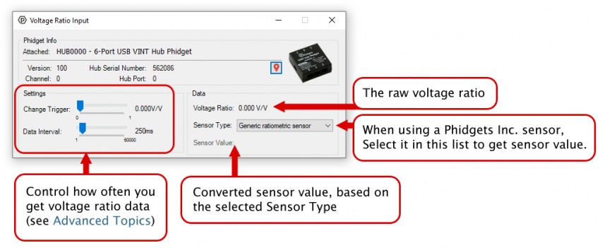
Voltage Ratio Input is one of the VINT Hub’s built-in Channel Classes. Any of these ports can act as a Voltage Ratio Input comparing the voltage provided to the voltage returned by the device, making it useful for connecting ratiometric sensors. The voltage ratio is reported in Volts per Volt. For example, if the Phidget is providing 5V and the sensor is sending back 2.5V, the ratio will be 0.5V/V.
Open Voltage Ratio Input Mode in the Control Panel to view your device’s voltage ratio.
Part 3: Create your Program
1. Setting up your Programming Environment
Part 4: Advanced Topics and Troubleshooting
Before you open a Phidget channel in your program, you can set these properties to specify which channel to open. You can find this information through the Control Panel.
1. Open the Control Panel and double-click on the red map pin icon:

2. The Addressing Information window will open. Here you will find all the information you need to address your Phidget in your program.

See the Phidget22 API for your language to determine exact syntax for each property.
The Change Trigger is the minimum change in the sensor data needed to trigger a new data event.
The Data Interval is the time (in ms) between data events sent out from your Phidget.
The Data Rate is the reciprocal of Data Interval (measured in Hz), and setting it will set the reciprocal value for Data Interval and vice-versa.
You can modify one or both of these values to achieve different data outputs. You can learn more about these properties here.
You can download the most recent HUB5000 firmware binary here:
To upgrade the firmware, go into the web configuration page as outlined in Part 1 of this User Guide. From there, click on "System", and upload this file by click on "select file" under the "Upgrade Firmware" section. After that, click on "Upgrade and Restart". You'll be instructed to wait a few minutes before logging back into the web interface. When you log in, you can confirm that the new version has successfully installed by checking to see if the firmware version listed in the "Status" section matches the first three numbers in the firmware file name that you downloaded. You can also check the version in the "Network Phidgets" tab on the Phidget Control Panel.
For an ethernet connected HUB5000 to be completely CE compliant, you must put a ferrite bead on the ethernet cable. Ferrite beads are only necessary when building the HUB5000 into a larger system that needs to be CE compliant. You can find clamp-on ferrite beads at electronic parts stores such as Digikey.
For more information on the capabilities of the ports on the VINT Hub, see the VINT Primer.
To get to the HUB5000's configuration page, open the Phidget Control Panel and find it under the "Network Phidgets" tab as outlined in Part 1 of this User Guide.
If the HUB5000 is in access point mode, you can access the configuration page through your phone: Connect to the HUB5000 Wi-Fi signal and enter the password on the sticker. Once you're connected, go to your internet app and go to address 192.168.100.1 . This address will take you to the configuration login page.
- Status: This section lists the hardware and firmware version of the HUB5000, along with the network addresses.
- Network: This section allows you to change the network connection settings and switch between Access Point mode and Client mode.
- Phidgets: This section has the Phidget Server controls(including controls to change the log level and view the log file). This section also contains the Web Server controls.
- System: This section allows you to change the password, and has other advanced settings including firmware upgrade and system/kernel logs.
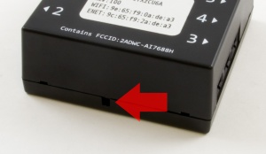
Pressing the reset button will reboot the HUB5000.
Holding the button down for 10 seconds before releasing will perform a reset. The reset will clear all settings, including the web configuration page password, and reset the Wi-Fi password to the one on the HUB5000's label.
As a last resort, you can perform a factory reset. Only perform a factory reset if the regular reset is not working, or there was an error during a firmware upgrade. Holding the button down before plugging in power, and keeping pressed for 15 seconds before releasing, will restore the original factory firmware.
When opening channels with Phidgets, you can set several properties to make sure you are accessing the precise channel you want. The HUB5000 has a unique serial number that can be used to find its ports or any VINT devices connected to them. If you want something more customizable and human-readable, you can use the device label instead. You can customize the device label by using writeDeviceLabel on the Hub object after it has been opened.
With the device label, you can address any of the VINT Hub's channels, or any connected VINT device channels. The device label will remain after the VINT Hub is unplugged as it is stored in flash memory.