|
Notice: This page contains information for the legacy Phidget21 Library. Phidget21 is out of support. Bugfixes may be considered on a case by case basis. Phidget21 does not support VINT Phidgets, or new USB Phidgets released after 2020. We maintain a selection of legacy devices for sale that are supported in Phidget21. We recommend that new projects be developed against the Phidget22 Library.
|
Digital Input Primer: Difference between revisions
No edit summary |
|||
| (13 intermediate revisions by 3 users not shown) | |||
| Line 1: | Line 1: | ||
[[Category: Primer]] | [[Category: Primer]] | ||
==Introduction== | |||
Digital Inputs can be used to convey the state of various devices such as push buttons, limit switches, relays, or logic level outputs. | Digital Inputs can be used to convey the state of various devices such as push buttons, limit switches, relays, or logic level outputs. | ||
| Line 6: | Line 8: | ||
Digital inputs are one of the easiest components to work with, since all that is required is a simple check to see which state they are in when an event triggers. | Digital inputs are one of the easiest components to work with, since all that is required is a simple check to see which state they are in when an event triggers. | ||
'''Note:''' The digital inputs on the [[1012_User_Guide|1012 - PhidgetInterfaceKit 0/16/16]] are active high rather than active low, so the instructions on this page do not apply. For information on the inputs on the 1012 please refer to the [[1012 User Guide#Digital Inputs|technical section of it's User Guide]]. | |||
==Specifications== | ==Specifications== | ||
| Line 11: | Line 15: | ||
===Digital Input Hardware Filter=== | ===Digital Input Hardware Filter=== | ||
There is built-in filtering on the digital input, to eliminate false triggering from electrical noise. | There is built-in filtering on the digital input, to eliminate false triggering from electrical noise. | ||
The digital input is first RC filtered by a 15K/100nF node, which will reject noise of higher frequency than | The digital input is first RC filtered by a 15K/100nF node, which will reject noise of higher frequency than 1kHz. | ||
This filter generally eliminates the need to shield the digital input from inductive and capacitive coupling likely to occur in wiring harnesses. | This filter generally eliminates the need to shield the digital input from inductive and capacitive coupling likely to occur in wiring harnesses. | ||
You can further reduce noise by externally filtering the input signal, but you will lose sensitivity in the process. | You can further reduce noise by externally filtering the input signal, but you will lose sensitivity in the process. | ||
===Digital Input Hysteresis=== | ===Digital Input Hysteresis=== | ||
The digital input has hysteresis - that is, it will hold | The digital input has hysteresis - that is, it will hold its current state (false or true), unless a large change occurs. | ||
To guarantee FALSE, the digital input must be at least 3.75V, and to guarantee TRUE, the digital input must be less than 1.25V. | To guarantee FALSE, the digital input must be at least 3.75V, and to guarantee TRUE, the digital input must be less than 1.25V. | ||
| Line 27: | Line 31: | ||
===Electrical Specifications=== | ===Electrical Specifications=== | ||
[[Image:digital_input.jpg|right|thumb|Schematic for a Phidgets digital input.]] | [[Image:digital_input.jpg|right|300px|link=|thumb|Schematic for a Phidgets digital input.]] | ||
The digital inputs have a built in 15K pull-up resistor. | The digital inputs have a built in 15K pull-up resistor. | ||
| Line 34: | Line 38: | ||
<br clear="all"> | <br clear="all"> | ||
==Using the Digital Inputs== | ==Using the Digital Inputs== | ||
Here are some circuit diagrams that illustrate how to connect various devices to the digital inputs on your Phidget. | Here are some circuit diagrams that illustrate how to connect various devices to the digital inputs on your Phidget. | ||
| Line 39: | Line 44: | ||
===Wiring a switch to a Digital Input=== | ===Wiring a switch to a Digital Input=== | ||
[[Image:switch_digital_input.jpg|right|thumb|Schematic for connecting a switch to a digital input.]] | [[Image:switch_digital_input.jpg|right|300px|link=|thumb|Schematic for connecting a switch to a digital input.]] | ||
Closing the switch causes the digital input to report TRUE. | Closing the switch causes the digital input to report TRUE. | ||
| Line 46: | Line 51: | ||
===Monitoring the Position of a Relay=== | ===Monitoring the Position of a Relay=== | ||
[[Image:relay_position.jpg|right|thumb|Schematic for connecting to a relay.]] | [[Image:relay_position.jpg|right|300px|link=|thumb|Schematic for connecting to a relay.]] | ||
The relay contact can be treated as a switch, and wired up similarly. | The relay contact can be treated as a switch, and wired up similarly. | ||
| Line 54: | Line 59: | ||
===Detecting an External Voltage with an N-Channel MOSFET=== | ===Detecting an External Voltage with an N-Channel MOSFET=== | ||
[[Image:external_voltage_mosfet.jpg|right|thumb|Schematic for detecting voltage with a NMOS transistor.]] | [[Image:external_voltage_mosfet.jpg|right|300px|link=|thumb|Schematic for detecting voltage with a NMOS transistor.]] | ||
A MOSFET can be used to detect the presence of an external voltage. | A MOSFET can be used to detect the presence of an external voltage. | ||
| Line 65: | Line 70: | ||
===Isolating a Digital Input with an Optocoupler=== | ===Isolating a Digital Input with an Optocoupler=== | ||
[[Image:isolating_digital_input_optocoupler.jpg|right|thumb|Schematic showing isolation of a digital input with an optocoupler.]] | [[Image:isolating_digital_input_optocoupler.jpg|right|300px|link=|thumb|Schematic showing isolation of a digital input with an optocoupler.]] | ||
When driving current through the LED, the Digital Input will report TRUE. | When driving current through the LED, the Digital Input will report TRUE. | ||
| Line 74: | Line 79: | ||
===Detecting an External Voltage with an NPN Transistor=== | ===Detecting an External Voltage with an NPN Transistor=== | ||
[[Image:external_voltage_npn.jpg|right|thumb|Schematic for detecting voltage with an NPN transistor.]] | [[Image:external_voltage_npn.jpg|right|thumb|300px|link=|Schematic for detecting voltage with an NPN transistor.]] | ||
This circuit can be used to measure if a battery is connected, or if 12V (for example) is on a wire. | This circuit can be used to measure if a battery is connected, or if 12V (for example) is on a wire. | ||
| Line 82: | Line 87: | ||
===Using a Capacitive or Inductive Proximity Switch=== | ===Using a Capacitive or Inductive Proximity Switch=== | ||
[[Image:proximity_switch.jpg|right|thumb|Schematic for connecting to a proximity switch.]] | [[Image:proximity_switch.jpg|right|thumb|300px|link=|Schematic for connecting to a proximity switch.]] | ||
Capacitive proximity switches can detect the presence of nearby non-metallic objects, whereas inductive proximity switches can detect only the presence of metallic objects. | Capacitive proximity switches can detect the presence of nearby non-metallic objects, whereas inductive proximity switches can detect only the presence of metallic objects. | ||
| Line 106: | Line 111: | ||
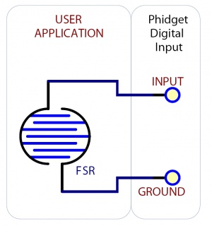
===Using an FSR or Variable Resistor as a Switch=== | ===Using an FSR or Variable Resistor as a Switch=== | ||
[[Image:fsr_switch.jpg|right|thumb|Schematic for using an FSR as a switch.]] | [[Image:fsr_switch.jpg|right|thumb|300px|link=|Schematic for using an FSR as a switch.]] | ||
The digital inputs can be easily wired to use many variable resistors as switches. | The digital inputs can be easily wired to use many variable resistors as switches. | ||
If the resistance falls below 3.75k Ohms, the Digital Input will go TRUE. | If the resistance falls below 3.75k Ohms, the Digital Input will go TRUE. | ||
If the resistance rises above 75k Ohms, the Digital Input will go FALSE. | If the resistance rises above 75k Ohms, the Digital Input will go FALSE. | ||
Latest revision as of 13:54, 25 April 2014
Introduction
Digital Inputs can be used to convey the state of various devices such as push buttons, limit switches, relays, or logic level outputs. They have two states: Low (or TRUE), and High (or FALSE). Any signal that is expected to interact with more than just these 2 states is inappropriate for this type of input.
Digital inputs are one of the easiest components to work with, since all that is required is a simple check to see which state they are in when an event triggers.
Note: The digital inputs on the 1012 - PhidgetInterfaceKit 0/16/16 are active high rather than active low, so the instructions on this page do not apply. For information on the inputs on the 1012 please refer to the technical section of it's User Guide.
Specifications
Digital Input Hardware Filter
There is built-in filtering on the digital input, to eliminate false triggering from electrical noise. The digital input is first RC filtered by a 15K/100nF node, which will reject noise of higher frequency than 1kHz. This filter generally eliminates the need to shield the digital input from inductive and capacitive coupling likely to occur in wiring harnesses. You can further reduce noise by externally filtering the input signal, but you will lose sensitivity in the process.
Digital Input Hysteresis
The digital input has hysteresis - that is, it will hold its current state (false or true), unless a large change occurs. To guarantee FALSE, the digital input must be at least 3.75V, and to guarantee TRUE, the digital input must be less than 1.25V.
Digital Input Sampling Characteristics
The state of the digital inputs are reported back to the PC periodically. During this sampling period, if a digital input was true for greater than 4.0ms, the digital input is guaranteed to be reported as true in software. This makes the digital input much more sensitive to reporting TRUE state, and makes it useful to watch for short events. Any Digital Input True events of less than 1.5ms are never reported.
Electrical Specifications
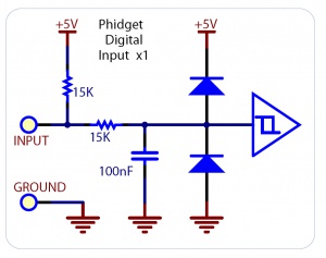
The digital inputs have a built in 15K pull-up resistor. By connecting external circuitry, and forcing the input to Ground, the Digital Input in software will read as TRUE. The default state is FALSE - when you have nothing connected, or your circuitry (switch, etc) is not pulling the input to ground.
Using the Digital Inputs
Here are some circuit diagrams that illustrate how to connect various devices to the digital inputs on your Phidget.
Wiring a switch to a Digital Input
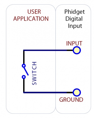
Closing the switch causes the digital input to report TRUE.
Monitoring the Position of a Relay
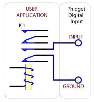
The relay contact can be treated as a switch, and wired up similarly. When the relay contact is closed, the Digital Input will report TRUE.
Detecting an External Voltage with an N-Channel MOSFET
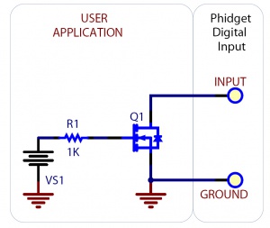
A MOSFET can be used to detect the presence of an external voltage. The external voltage will turn on the MOSFET, causing it to short the Digital Input to Ground. If the MOSFET is conducting > 270uA, the Digital Input is guaranteed to report TRUE. If the MOSFET is conducting < 67uA, the Digital Input is guaranteed to report FALSE. The voltage level required to turn on the MOSFET depends on the make of of MOSFET you are using. Typical values are 2V-6V.
Isolating a Digital Input with an Optocoupler
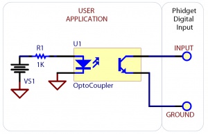
When driving current through the LED, the Digital Input will report TRUE. The amount of current required will depend on the optocoupler used. Design to sink at least 270uA to cause the digital input to report TRUE, and less than 67uA to report FALSE.
Detecting an External Voltage with an NPN Transistor
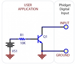
This circuit can be used to measure if a battery is connected, or if 12V (for example) is on a wire. By designing to have Collector-Emitter current > 270uA, the digital input will report TRUE.
Using a Capacitive or Inductive Proximity Switch
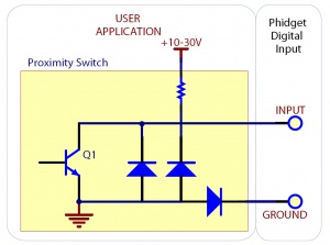
Capacitive proximity switches can detect the presence of nearby non-metallic objects, whereas inductive proximity switches can detect only the presence of metallic objects. To properly interface one of these proximity switches to the digital inputs, a 3-wire proximity switch is required, as well as an external power supply. We have checked the following switch from Automation Direct to verify that it works with the Digital Inputs. Similar capacitive or inductive proximity switches from other manufacturers should work just as well.
| Manufacturer | Web Page | Capacitive Part No. | Inductive Part No. |
|---|---|---|---|
| Automation Direct | www.automationdirect.com | CT1 Series | AM1 Series |
Using an FSR or Variable Resistor as a Switch
The digital inputs can be easily wired to use many variable resistors as switches. If the resistance falls below 3.75k Ohms, the Digital Input will go TRUE. If the resistance rises above 75k Ohms, the Digital Input will go FALSE.