|
Notice: This page contains information for the legacy Phidget21 Library. Phidget21 is out of support. Bugfixes may be considered on a case by case basis. Phidget21 does not support VINT Phidgets, or new USB Phidgets released after 2020. We maintain a selection of legacy devices for sale that are supported in Phidget21. We recommend that new projects be developed against the Phidget22 Library.
|
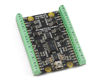
1012 User Guide
| |
| Go to this device's product page |
Getting Started
Checking the Contents
|
You should have received:
|
In order to test your new Phidget you will also need:
| |
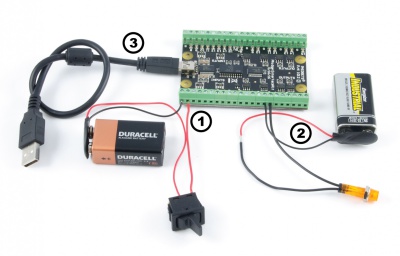
Connecting the Pieces
|
| |
Testing Using Windows 2000 / XP / Vista / 7
Make sure you have the current version of the Phidget library installed on your PC. If you don't, follow these steps:
- Go to the Quick Downloads section on the Windows page
- Download and run the Phidget21 Installer (32-bit, or 64-bit, depending on your system)
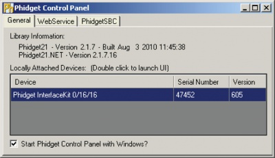
- You should see the
 icon on the right hand corner of the Task Bar.
Running Phidgets Sample Program
Double clicking on the ![]() icon loads the Phidget Control Panel; we will use this program to ensure that your new Phidget works properly.
icon loads the Phidget Control Panel; we will use this program to ensure that your new Phidget works properly.
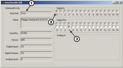
The source code for the InterfaceKit-Full sample program can be found in the quick downloads section on the C# Language Page. If you'd like to see examples in other languages, you can visit our Languages page.
Updating Device Firmware
If an entry in this list is red, it means the firmware for that device is out of date. Double click on the entry to be given the option of updating the firmware. If you choose not to update the firmware, you can still run the example for that device after refusing.
|
Double Click on the |
| |
|
|
Testing Using Mac OS X
- Go to the Quick Downloads section on the Mac OS X page
- Download and run the Phidget OS X Installer
- Click on System Preferences >> Phidgets (under Other) to activate the Preference Pane
- Make sure that the Phidget InterfaceKit 0/16/16 is properly attached.
- Double Click on Phidget InterfaceKit 0/16/16 in the Phidget Preference Pane to bring up the InterfaceKit-Full Sample program. This program will function in a similar way as the Windows version.
Using Linux
For a step-by-step guide on getting Phidgets running on Linux, check the Linux page.
Using Windows Mobile / CE 5.0 / CE 6.0
For a step-by-step guide on getting Phidgets running on Windows CE, check the Windows CE page.
Technical Details
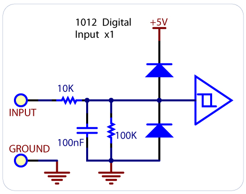
Digital Inputs
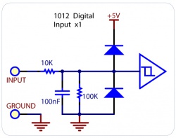
There is built-in filtering on the digital input, to eliminate false triggering from electrical noise. The digital input is first RC filtered by a 10K/100nF node, which will reject noise of higher frequency than 1Khz. This filter generally eliminates the need to shield the digital input from inductive and capacitive coupling likely to occur in wiring harnesses.
Monitoring a Switch
Full-Sized Image
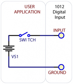
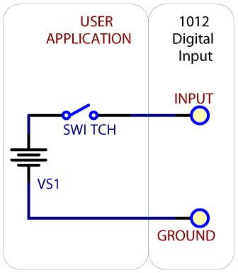
To test your digital input, wire it up to a switch as shown in the diagram. The power supply VS1 needs to be within 4-30V DC in order to guarantee a response from the digital input when the switch is closed.
Monitoring the Position of a Relay
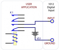
If you have a double-pole relay (that is, a relay that is designed to close two switches at once with the same control input), you can switch a load with one pole, and monitor the state of the relay with the other pole. This can come in handy as a safety feature- if the relay were to fail, your software would normally not have any way of knowing.
Functional Block Diagram
Unlike typical Phidgets Digital Inputs, these are capable of receiving up to 30VDC. These inputs are active high: A voltage of 4VDC to 30VDC will be read as True or logical 1; below 1VDC will be read as a False or logical 0. The input is high impedance, which means current flowing into the Phidget device will be limited. Ground terminals are provided in multiple locations along the input terminal strip; it is recommended that the ground terminal located nearest the input terminal be used.
Open Collector Digital Outputs
For more information, check the Open Collector Digital Output Primer.
API
We document API Calls specific to this product in this section. Functions common to all Phidgets and functions not applicable to this device are not covered here. This section is deliberately generic. For calling conventions under a specific language, refer to the associated API manual in the Quick Downloads section for that language. For exact values, refer to the device specifications.
Functions
int InputCount() [get] : Constant = 16
- Returns the number of digital inputs supported by this PhidgetInterfaceKit.
bool InputState(int InputIndex) [get]
- Returns the state of a particular digital input. Digital inputs read True where they are activated and false when they are in their default state.
int OutputCount() [get] : Constant = 16
- Returns the number of digital outputs supported by this PhidgetInterfaceKit.
bool OutputState (int OutputIndex) [get,set]
- Sets/returns the state of a digital output. Setting this to true will activate the output, False is the default state. Reading the OutputState immediately after setting it will not return the value set - it will return the last state reported by the Phidget.
Events
OnInputChange(int InputIndex, bool State) [event]
- An event that is issued when the state of a digital input changes.
OnOutputChange(int OutputIndex, bool State), [event]
- An event that is issued when the state of a digital output changes.
Product History
| Date | Board Revision | Device Version | Comment |
|---|---|---|---|
| January 2003 | 0 | 600 | Product Release |
| January 2004 | 0 | 601 | Added State Echoing |
| June 2006 | 0 | 602 | Fixed flipped protocol bits |
| May 2007 | 0 | 603 | |
| July 2007 | 0 | 604 | |
| January 2008 | 0 | 605 | Added Digital Input Filtering |
| September 2008 | 1 | 605 | Added Digital Input Filtering |
| September 2010 | 2 | 605 | Smaller Terminal blocks, Mini-USB connector, red Digital Outputs and green Digital Inputs LEDs, added two +5V terminal blocks |