|
Notice: This page contains information for the legacy Phidget21 Library. Phidget21 is out of support. Bugfixes may be considered on a case by case basis. Phidget21 does not support VINT Phidgets, or new USB Phidgets released after 2020. We maintain a selection of legacy devices for sale that are supported in Phidget21. We recommend that new projects be developed against the Phidget22 Library.
|
3618 User Guide
| |
| Go to this device's product page |
Introduction
This manual describes how to connect and control the 3618 LED module using Phidgets I/O boards and relays.
I/O Boards:
Relays:
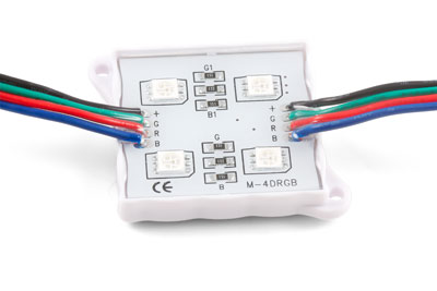
Connecting the LED Module
Connecting to the 1012 - PhidgetInterfaceKit 0/16/16
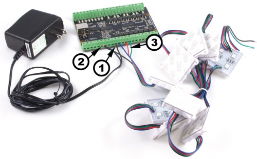
Note: Be aware that the LEDs can get damaged if the proper polarity is not respected: Anode (+), Cathode (-). |
| |
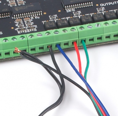
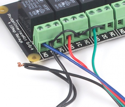
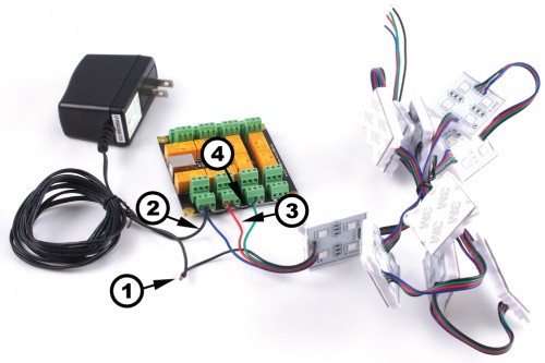
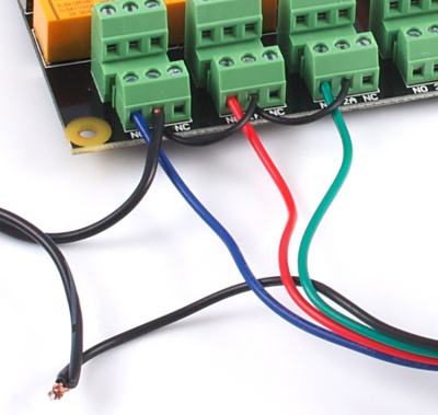
Connecting to the 1014 - PhidgetInterfaceKit 0/0/4
If you connect the power supply live wire to the NC (Normally Closed) terminal, the LED strip will be ON when the switch is off. Note: Be aware that the LEDs can get damaged if the proper polarity is not respected: Anode (+), Cathode (-). |
| |
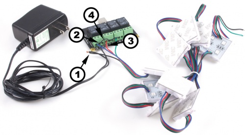
Connecting to the 1017 - PhidgetInterfaceKit 0/0/8
Note: Be aware that the LEDs can get damaged if the proper polarity is not respected: Anode (+), Cathode (-). |
| |