|
Notice: This page contains information for the legacy Phidget21 Library. Phidget21 is out of support. Bugfixes may be considered on a case by case basis. Phidget21 does not support VINT Phidgets, or new USB Phidgets released after 2020. We maintain a selection of legacy devices for sale that are supported in Phidget21. We recommend that new projects be developed against the Phidget22 Library.
|
3615 User Guide
| |
| Go to this device's product page |
Introduction
This manual describes how to connect and control the 3615 LED strip using Phidgets I/O boards and relays.
I/O Boards:
Relays:
- 1014 - PhidgetInterfaceKit 0/0/4
- 1017 - PhidgetInterfaceKit 0/0/8
- 3051 - Dual Relay Board
- 3052 - SSR Relay Board
- 3053 - Dual SSR Relay Board
Connecting the LED Strip
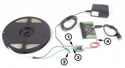
Connecting to the 1012 - PhidgetInterfaceKit 0/16/16
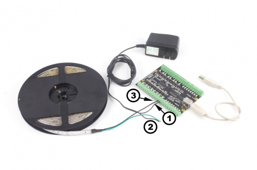
- Connect the ground (-) wire from your power supply to the ground terminal (G) on the 1012.
- Connect the white anode wire from the LED strip to the power supply live wire (+).
- Connect the black cathode wire from the LED strip to the digital output terminal.
Note: Be aware that the LEDs can get damaged if the proper polarity is not respected: Anode (+), Cathode (-).
Connecting to the 1014 - PhidgetInterfaceKit 0/0/4
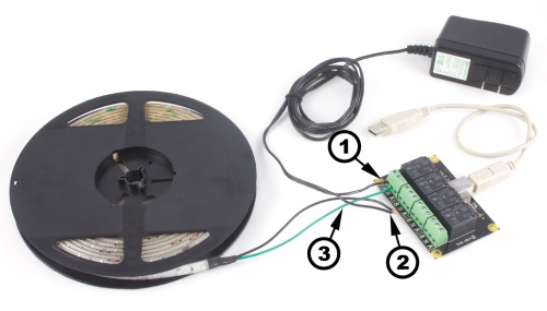
- Connect the live (+) wire from your power supply to the NO (Normally Open) connector on the 1017.
- Connect the black cathode wire from the LED strip to the power supply ground wire (-).
- Connect the white anode wire from the LED strip to the common connector on the 1017.
If you connect the power supply live wire to NC (Normally Closed) terminal, the LED strip will be ON when the switch is off.
Note: Be aware that the LEDs can get damaged if the proper polarity is not respected: Anode (+), Cathode (-).
Connecting to the 1017 - PhidgetInterfaceKit 0/0/8
- Connect the live (+) wire from your power supply to the NO (Normally Open) connector on the 1017.
- Connect the black cathode wire from the LED strip to the power supply ground wire (-).
- Connect the white anode wire from the LED strip to the common connector on the 1017.
If you connect the power supply live wire to NC (Normally Closed) terminal, the LED strip will be ON when the switch is off.
Note: Be aware that the LEDs can get damaged if the proper polarity is not respected: Anode (+), Cathode (-).
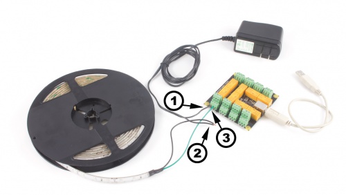
Connecting to the 3051 - Dual Relay Board
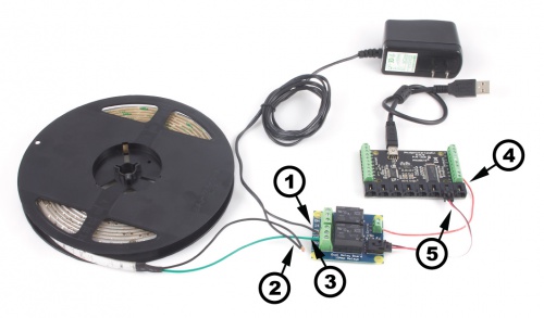
- Connect the live (+) wire from your power supply to the NO (Normally Open) connector on the 3051.
- Connect the black cathode wire from the LED strip to the power supply ground wire (-).
- Connect the white anode wire from the LED strip to the common connector on the 3051.
- Connect one of the two control terminals on the 3051 to a Digital Output on the 1018.
- Connect the 3051 to the 1018 using the sensor cable.
If you connect the white anode wire to NC (Normally Closed) terminal, the LED strip will be ON when the switch is off.
Note: Be aware that the LEDs can get damaged if the proper polarity is not respected: Anode (+), Cathode (-).
Connecting to the 3052, 3053 - SSR Relay Boards
- Connect the live (+) wire from your power supply to one of the output terminals on the SSR Board.
- Connect the black cathode wire from the LED strip to the power supply ground wire (-).
- Connect the white anode wire from the LED strip to the other output terminal on the SSR board.
- Attach the SSR Board to your PhidgetInterfaceKit by connecting the positive (red) wire to a digital output and the ground (black) wire to a ground terminal on the InterfaceKit.
Note: Be aware that the LEDs can get damaged if the proper polarity is not respected: Anode (+), Cathode (-).