|
Notice: This page contains information for the legacy Phidget21 Library. Phidget21 is out of support. Bugfixes may be considered on a case by case basis. Phidget21 does not support VINT Phidgets, or new USB Phidgets released after 2020. We maintain a selection of legacy devices for sale that are supported in Phidget21. We recommend that new projects be developed against the Phidget22 Library.
|
3531 User Guide
| |
| Go to this device's product page |
Getting Started
Checking the Contents
|
You should have received:
|
In order to test your new Phidget you will also need:
| |
Connecting the Pieces
|
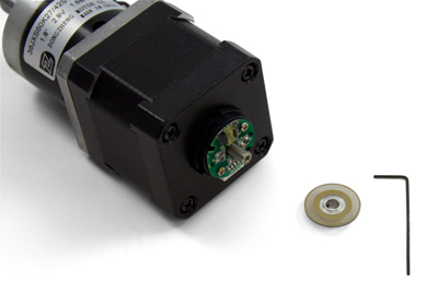
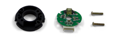
Take the plastic base, the encoder PCB, and the two screws (the screws should be inside the encoder cap). Place the PCB with the white connector facing downward so that it fits into the space on the plastic base. Take care not to touch the optical sensor on top of the PCB, because your fingerprints could affect the operation of the sensor. Place the screws in the two holes in the PCB. |
| |
|
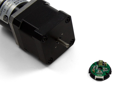
Line the parts up with the mounting holes on the back of the motor. It doesn't matter which way the encoder is facing, but for cable management purposes you may want to have the connector facing the same direction as the motor's wires. Screw the parts onto the back of the motor, tightening until there is no visible gap between the PCB and the plastic base. Do not over-tighten. |
|
|
Get the encoder disk and hex key. Do not touch the surface of the encoder disk, as your fingerprints could affect the operation of the optical sensor. Place the encoder disk on the rear shaft of the motor with the metal coupler facing outward. Slide the encoder disk until the surface of the disk is approximately 1.5mm from the optical sensor on the PCB. Use the hex key to tighten the set-screw on the coupler of the encoder disk. |
| |
|
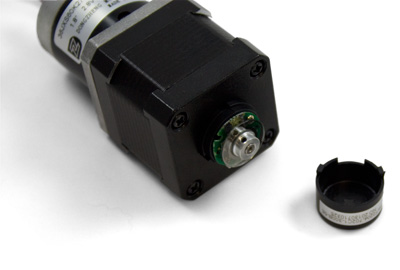
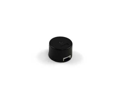
Double check everything before attaching the plastic cap; it is very difficult to remove once it snaps in place. |
| |
|
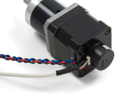
Attach the included encoder cable and you're all done! For further instructions, visit the user guide for the motor controller and encoder interface Phidget that you're using. |
|