|
Notice: This page contains information for the legacy Phidget21 Library. Phidget21 is out of support. Bugfixes may be considered on a case by case basis. Phidget21 does not support VINT Phidgets, or new USB Phidgets released after 2020. We maintain a selection of legacy devices for sale that are supported in Phidget21. We recommend that new projects be developed against the Phidget22 Library.
|
3175 User Guide
| |
| Go to this device's product page |
Getting Started
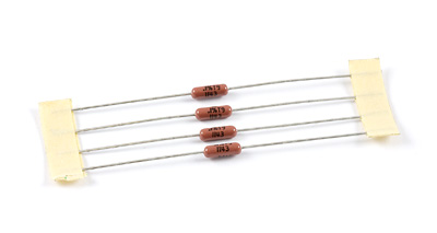
| The 3175 RTD Resistor Kit includes four pieces of 1.00 KiloOhm resistors. These precision resistors are used to interface Platinum RTDs to the 1046 PhidgetBridge. Platinum RTDs (Resistive Thermal Devices) are used to make very precise temperature measurements. RTDs are very accurate, and will measure temperatures up to 500 degrees Celsius. The electrical resistance of the RTD changes predictably with temperature, and RTDs are the most accurate commonly available temperature sensors. Measuring the resistance of an RTD requires accurate components all through the system - otherwise there is no point in paying for an RTD. The resistors in the 3175 RTD Resistor Kit have a worst case error of 0.1% - translating to a typical temperature error of 0.05 Celsius. The resistors also change their resistance very little with temperature - ambient temperature variation is a significant source of error for thermocouples. RTDs with a well designed data acquisition system will not be subject to these temperature variation errors. Wiring the resistors to your RTD allows the 1046 PhidgetBridge to convert the resistances into a voltage, which it then measures. The PhidgetBridge is by far the most precise Phidget device for measuring voltage. The PhidgetBridge also cancels the errors resulting from USB voltage variation. | 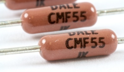
|
Measuring Resistive Thermal Devices (RTD)
Using a Wheatstone Bridge
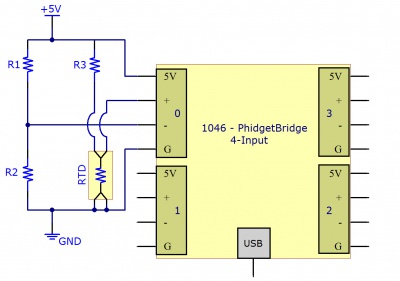
A Wheatstone bridge is the classic method of measuring unknown resistances, and requires three resistors of known values. It uses the current in each leg of the bridge to create a voltage differential between both voltage dividers. Using the voltage differential and the three known resistors, the resistance of the fourth resistor can be determined.
To determine the resistance of the RTD, the following formula can be used:
![R_{RTD} = \frac{R_3 \times [R_2 + V_B \times (R_1 + R_2)]}{R_1 - (R_1 + R_2) \times V_B }](https://wikimedia.org/api/rest_v1/media/math/render/svg/f9b5eaa5340732e841a084db3919b85e2ae44eb0)
Where is the Bridge Value given by the PhidgetBridge (in mV/V) , and , and are the resistances of the known resistors.


Using a Voltage Divider
The alternate method requires only two resistors. This reduces the amount of error that can be introduced into the system due to resistor tolerances. A voltage is applied to the two resistors and the RTD in series. The voltage drop across the RTD is measured. Using the voltage drop and the values of the two resistors, the resistance of the RTD can be determined.
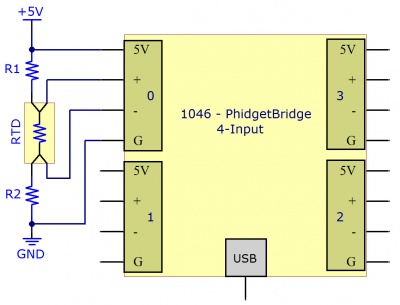
To determine the resistance of the RTD, the following formula can be used:

Where is the Bridge Value given by the PhidgetBridge (in mV/V) , and and are the resistances of the known resistors.
Getting Higher Accuracy
In order to get the highest accuracy from the RTD, consider the following:
- Use resistors with a high degree of tolerance. There will be less variability in the manufacturing of 0.1% resistors when compared to 1% resistors.
- Measure the known resistors with an ohmmeter. By obtaining the most accurate measurements for the known resistances, the formula will result in a more accurate measurement of the RTD.
- Use a moving average when obtaining the Bridge Value to reduce the amount of noise in the measured signal.
- Estimate or Measure the resistance of the +5V and GND wires between the RTD and the 1046 PhidgetBridge. Add this resistance to the two resistors.
- Turn off the power to the RTD (by disabling the channel on the PhidgetBridge) to reduce self-heating of the RTD.
- By using higher resistor values (> 1 Kilo ohm), there will be less self-heating of the RTD, but the resolution of the measurement will be reduced somewhat. We recommend 1 Kilo Ohm resistors as a reasonable trade off.
Using the PhidgetBridge Code Sample on Windows
| The PhidgetBridge Bridge-full application will allow you to verify that your PhidgetBridge is working, and that your wiring is functional. Please check the 1046 manual for instructions on launching the application. The PhidgetBridge has the ability to amplify the measured signal - it was built to measure extremely small signals. Amplification is not necessary with RTDs, so we recommend leaving the gain set to 1. If you do decide to amplify, please study the limitations of amplification on the 1046, to ensure that the most extreme temperatures encountered do not cause the amplifier to reach its limit during operation, blinding your application from further changes coming from the RTD. If amplifier is in danger of saturating (reaching the limit), an Overrange error will be thrown. When using the Bridge-full application, remember to check the Enabled box, to power up the bridge and start measurements. | 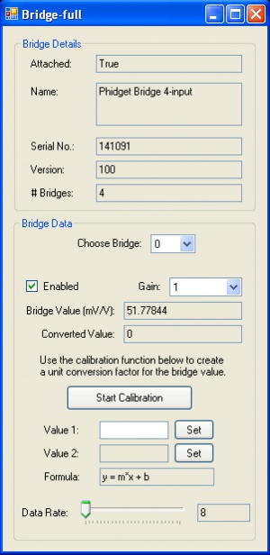
|
Applying the Formula
There are several standards for RTDs. Common RTDs are built from platinum, the most common models being Pt100 and Pt1000. The 100 or 1000 refers to the resistance of the RTD and 0 Celsius. We have calculated formulas for the PT100 and PT1000 standards to convert the Bridge Value in (mv/V) directly into a temperature.
- where VB is the BridgeValue given by the PhidgetBridge (in mV/V), and

- R0 is the resisitance of the RTD at 0°C (100 for Pt100 and 1000 for Pt1000)
Using the Resistor Kit with non-standard RTDs and thermistors
Some RTDs are not standardized, so we cannot provide a formula to convert the Bridge Value to temperature. The following formula will calculate the resistance of the RTD or thermistor from the bridge voltage - a good start for computing the temperature. To calculate temperature, check the manufacturer’s data sheet for formulas or tables for converting resistance to temperature.

Self heating of RTDs
By passing current through the RTD, it will heat up, distorting your temperature measurement. To determine the power dissipated as heat in the RTD use the following formula,
- where RRTD is the resistance of your RTD.
The RTD manufacturer will often specify the temperature increase of the RTD as a function of power (watts). This

power was calculated in the previous equation. This temperature increase will depend on if it is attached to a larger object that will sink the heat away, or if there is air movement over the RTD. A simple way to reduce the effects of self-heating is to enable the bridge in software during the measurement period, and disable the bridge until the next measurement.
Product History
| Date | Board Revision | Device Version | Comment |
|---|---|---|---|
| December 2011 | 0 | N/A | Product Release |