|
Notice: This page contains information for the legacy Phidget21 Library. Phidget21 is out of support. Bugfixes may be considered on a case by case basis. Phidget21 does not support VINT Phidgets, or new USB Phidgets released after 2020. We maintain a selection of legacy devices for sale that are supported in Phidget21. We recommend that new projects be developed against the Phidget22 Library.
|
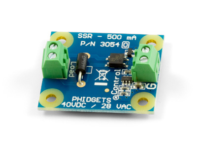
3054 User Guide
| |
| Go to this device's product page |
Getting Started
Checking the Contents
|
You should have received:
|
In order to test your new Phidget you will also need:
| |
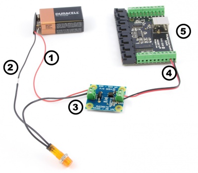
Connecting the Pieces
|
| |
Testing Using Windows 2000 / XP / Vista / 7
Make sure you have the current version of the Phidget library installed on your PC. If you don't, follow these steps:
- Go to the Quick Downloads section on the Windows page
- Download and run the Phidget21 Installer (32-bit, or 64-bit, depending on your system)
- You should see the
 icon on the right hand corner of the Task Bar.
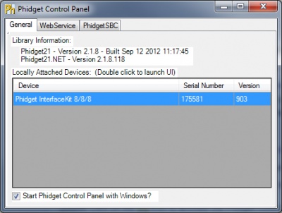
Running Phidgets Sample Program
Double clicking on the ![]() icon loads the Phidget Control Panel; we will use this program to ensure that your new Phidget works properly.
icon loads the Phidget Control Panel; we will use this program to ensure that your new Phidget works properly.
The source code for the InterfaceKit-full sample program can be found in the quick downloads section on the C# Language Page. If you'd like to see examples in other languages, you can visit our Languages page.
Updating Device Firmware
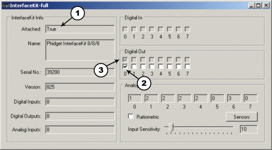
If an entry in this list is red, it means the firmware for that device is out of date. Double click on the entry to be given the option of updating the firmware. If you choose not to update the firmware, you can still run the example for that device after refusing.
|
Double Click on the |
| |
|
|
Testing Using Mac OS X
- Go to the Quick Downloads section on the Mac OS X page
- Download and run the Phidget OS X Installer
- Click on System Preferences >> Phidgets (under Other) to activate the Preference Pane
- Make sure that the is properly attached.
- Double Click on in the Phidget Preference Pane to bring up the Sample program. This program will function in a similar way as the Windows version.
Using Linux
For a step-by-step guide on getting Phidgets running on Linux, check the Linux page.
Using Windows Mobile / CE 5.0 / CE 6.0
For a step-by-step guide on getting Phidgets running on Windows CE, check the Windows CE page.
Technical Details
Solid State Relays
Solid State Relays, or SSRs, are devices designed to operate like standard relays but without mechanical motion. Built instead out of silicon transistors, SSRs allow currents and voltages to be switched by simple digital signals from a microprocessor or any other device that can supply the small amount of current needed to activate the SSR’s internal switching mechanism. For more information on solid state relays, refer to the SSR Primer.
Protection Devices
The SSR Board is safe to use with sensitive control devices like microprocessors, and will not damage a Phidget device or your PC. Optoisolation between the control inputs and outputs of the SSR in the form of a GaAs LED paired with a set of optically-controlled MOSFETs provides protection from output to input. An on-board 47V bidirectional transorb across the relay output protects the board from static electricity and surges from inductive loads.
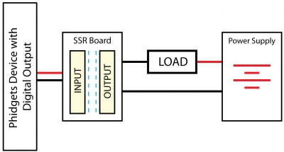
Using the SSR Board
|
Using the SSR Relay Board in your application is typically done according to the diagram on the right, though there are other implementations for it as well. |
| |
Product History
| Date | Board Revision | Device Version | Comment |
|---|---|---|---|
| January 2013 | 0 | N/A | Product Release |