|
Notice: This page contains information for the legacy Phidget21 Library. Phidget21 is out of support. Bugfixes may be considered on a case by case basis. Phidget21 does not support VINT Phidgets, or new USB Phidgets released after 2020. We maintain a selection of legacy devices for sale that are supported in Phidget21. We recommend that new projects be developed against the Phidget22 Library.
|
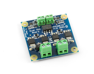
3053 User Guide
| |
| Go to this device's product page |
Getting Started
Checking the Contents
|
You should have received:
|
In order to test your new Phidget you will also need:
| |
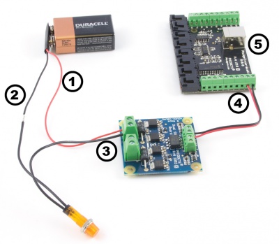
Connecting the Pieces
|
| |
Testing Using Windows 2000 / XP / Vista / 7
Make sure you have the current version of the Phidget library installed on your PC. If you don't, follow these steps:
- Go to the Quick Downloads section on the Windows page
- Download and run the Phidget21 Installer (32-bit, or 64-bit, depending on your system)
- You should see the
 icon on the right hand corner of the Task Bar.
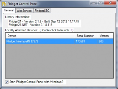
Running Phidgets Sample Program
Double clicking on the ![]() icon loads the Phidget Control Panel; we will use this program to ensure that your new Phidget works properly.
icon loads the Phidget Control Panel; we will use this program to ensure that your new Phidget works properly.
The source code for the InterfaceKit-full sample program can be found in the quick downloads section on the C# Language Page. If you'd like to see examples in other languages, you can visit our Languages page.
Updating Device Firmware
If an entry in this list is red, it means the firmware for that device is out of date. Double click on the entry to be given the option of updating the firmware. If you choose not to update the firmware, you can still run the example for that device after refusing.
|
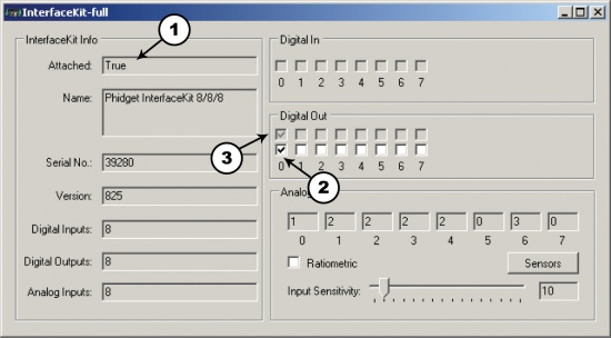
Double Click on the |
| |
|
|
Testing Using Mac OS X
- Go to the Quick Downloads section on the Mac OS X page
- Download and run the Phidget OS X Installer
- Click on System Preferences >> Phidgets (under Other) to activate the Preference Pane
- Make sure that the is properly attached.
- Double Click on in the Phidget Preference Pane to bring up the Sample program. This program will function in a similar way as the Windows version.
Using Linux
For a step-by-step guide on getting Phidgets running on Linux, check the Linux page.
Using Windows Mobile / CE 5.0 / CE 6.0
For a step-by-step guide on getting Phidgets running on Windows CE, check the Windows CE page.
Technical Details
Solid State Relays
Solid State Relays, or SSRs, are devices designed to operate like standard relays but without mechanical motion. Built instead out of silicon transistors, SSRs allow currents and voltages to be switched by simple digital signals from a microprocessor or any other device that can supply the small amount of current needed to activate the SSR’s internal switching mechanism. For more information on solid state relays, refer to the SSR Primer.
Using the SSR Board
|
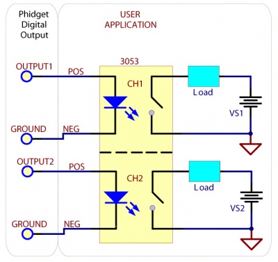
Using the SSR Relay Board in your application is typically done according to the diagram on the right, though there are other implementations for it as well. The SSR control inputs can be controlled with a wide range of voltage levels between 3 and 30V. Be sure to match the polarity of the control signal with the +/- labels on the input terminal blocks. One concern with any type of relay is the turn-on and turn-off times. Since the SSR Board uses optoisolation, the turn-on delay depends on how strong the control signal is, while the turn-off delay is quite constant, and quick. The 3053 uses internal circuitry to keep the current of the control signal around 10mA, no matter how what voltage level is used. To improve the turn-on time of the SSR, a short current spike (approximately 35mA for 300μs) at turn-on is possible if your control signal can provide it. This allows the SSR to turn on quicker, reducing heating during the turn-on transition. If your control signal is not able to provide the 35mA, the SSR will turn on anyway, but will take up to 50% longer. If the Phidget InterfaceKit 8/8/8 is being used to drive the input, the control signal has an output resistance of about 250 Ohms, and the SSR has a turn-on time of 1.90ms. The turn-off time is approximately 160μs. |
| |
Isolation and Protection Devices
The SSR Board is safe to use with sensitive control devices like microprocessors, and will not damage a Phidget device or your PC. This is achieved through the use of an optoisolation chip - creating a physical barrier between the SSR control inputs and the potentially high voltage and high current outputs. In addition to the optoisolation between the inputs and outputs, there is an on-board 47V voltage supression device across the relay output that protects the board from static electricity and surges from inductive loads. To protect the optoisolation LEDs from potential overcurrent on the inputs, a transistor-based current limiting circuit has been added. The circuit limits the constant current travelling through the LEDs to 10mA, regardless of the input voltage. The transistors dissipate what would have been extra current in the form of heat. The 3053 Dual SSR Board comprises of two channels. Both channels are electrically and physically isolated from each other, and are controlled individually.
Warning
The SSR Board is able to safely switch at a speed of 20Hz. This board is not intended as a high frequency switch due to the extreme heating that will occur. Although it is possible to switch the SSR Board at up to 300Hz, it easily produces enough heat to liquefy the solder underneath the transistors (which requires at least 240ºC) at a 3A load.
Product History
| Date | Board Revision | Device Version | Comment |
|---|---|---|---|
| May 2010 | 0 | N/A | Product Release |