|
Notice: This page contains information for the legacy Phidget21 Library. Phidget21 is out of support. Bugfixes may be considered on a case by case basis. Phidget21 does not support VINT Phidgets, or new USB Phidgets released after 2020. We maintain a selection of legacy devices for sale that are supported in Phidget21. We recommend that new projects be developed against the Phidget22 Library.
|
1134 User Guide
| |
| Go to this device's product page |
Getting Started
Checking the Contents
|
You should have received:
|
In order to test your new Phidget you will also need:
| |
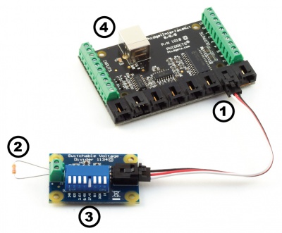
Connecting the Pieces
|
| |
Testing Using Windows 2000 / XP / Vista / 7
Make sure you have the current version of the Phidget library installed on your PC. If you don't, follow these steps:
- Go to the Quick Downloads section on the Windows page
- Download and run the Phidget21 Installer (32-bit, or 64-bit, depending on your system)
- You should see the
 icon on the right hand corner of the Task Bar.
Running Phidgets Sample Program
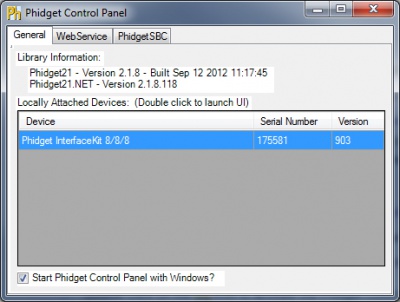
Double clicking on the ![]() icon loads the Phidget Control Panel; we will use this program to ensure that your new Phidget works properly.
icon loads the Phidget Control Panel; we will use this program to ensure that your new Phidget works properly.
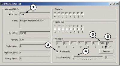
The source code for the InterfaceKit-full sample program can be found in the quick downloads section on the C# Language Page. If you'd like to see examples in other languages, you can visit our Languages page.
Updating Device Firmware
If an entry in this list is red, it means the firmware for that device is out of date. Double click on the entry to be given the option of updating the firmware. If you choose not to update the firmware, you can still run the example for that device after refusing.
|
Double Click on the |
| |
|
| |
|
|
Testing Using Mac OS X
- Go to the Quick Downloads section on the Mac OS X page
- Download and run the Phidget OS X Installer
- Click on System Preferences >> Phidgets (under Other) to activate the Preference Pane
- Make sure that the is properly attached.
- Double Click on in the Phidget Preference Pane to bring up the Sample program. This program will function in a similar way as the Windows version.
Using Linux
For a step-by-step guide on getting Phidgets running on Linux, check the Linux page.
Using Windows Mobile / CE 5.0 / CE 6.0
For a step-by-step guide on getting Phidgets running on Windows CE, check the Windows CE page.
Technical Details
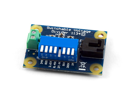
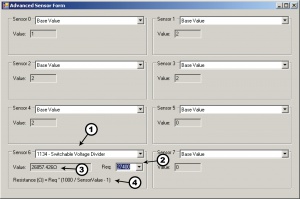
The 1134 Switchable Voltage Divider is a voltage divider with switches. The switches can be used to control which resistors are used in the voltage divider. From left to right, the resistance values (in Ohms) are 249, 820, 2.61K,8.45K, 27.4K, 91K, 300K and 1M. It is possible to have multiple switches flipped, putting the corresponding resistors in parallel.
Formulas
The Formula to translate SensorValue into resistance is:

Where Req</sub is the equivalent resistance of the switches that are flipped on in Ohms. The Switchable Voltage Divider has an internal buffer on the output. This allows the output to be read without distortion caused by the device reading the measurement, such as the PhidgetInterfaceKit.
Configuring the Voltage Divider
| To optimize the voltage divider to meet your needs, you have to adjust the switchable resistance to match the characteristics of your chosen variable resistor. First, adjust the resistance for no stimuli on your sensor, then apply maximum stimuli and make sure that the Sensor Value stays within a range that gives you an acceptable resolution. The formula is most accurate at a SensorValue of 500, with an error of 0.4%. At 100 and 900, the error increases to approximately 1.1% and at 50 and 950, it increases to 2.1%. As a general rule, if the SensorValue is over 900, a lower resistance should be switched in. If the SensorValue is below 100, a higher switch should be toggled. Continue adjusting the switches until you find an acceptable range. | 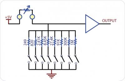
|
Warning: It is possible for the 1134 to apply up to 5V to the variable resistor. If the resistor cannot handle this voltage, it can be damaged. The 1134 is a very simple way of measure resistance. When interfacing to sensors with small resistances (like 100 ohm RTDs, for instance), large currents can flow - up to 30 mA. This level of current may cause substantial heating in the variable resistor, distorting the measurement or even possibly permanently damaging it.
Variable resistance sensors
Here are some interesting variable resistance sensors that could be used with the Voltage Divider.
| Sensor Type | Manufacturer | Example | Digikey Search |
| Light Sensors | Advanced Photonics | PDV-P9003-1 | photcell |
| Force Sensors | CUI Inc. | IESP-12 | force sensor |
| Thermistors | US Sensor | 615-1037-ND | termistor radial |
| Bend Sensors | imagesco.com | FLX-01 | n/a |
Other Interfacing Alternatives
If you want maximum accuracy, you can use the RawSensorValue property from the PhidgetInterfaceKit. To adjust a formula, substitute (SensorValue) with (RawSensorValue / 4.095) If the sensor is being interfaced to your own Analog to Digital Converter and not a Phidget device, our formulas can be modified by replacing (SensorValue) with (Vin * 200). It is important to consider the voltage reference and input voltage range of your ADC for full accuracy and range.
Analog Input Cable Connectors
|
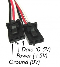
Each Analog Input uses a 3-pin, 0.100 inch pitch locking connector. Pictured here is a plug with the connections labelled. The connectors are commonly available - refer to the Analog Input Primer for manufacturer part numbers. |
| |
API
Phidget analog sensors do not have their own API- they simply output a voltage that is converted to a digital value and accessed through the "Sensor" properties and events on the PhidgetInterfaceKit API. It is not possible to programmatically identify which sensor is attached to the Analog Input. To an InterfaceKit, every sensor looks the same. Your application will need to apply formulas from this manual to the SensorValue (an integer that ranges from 0 to 1000) to convert it into the units of the quantity being measured. For example, this is how you would use a temperature sensor in a C# program:
 // set up the interfacekit object
InterfaceKit IFK = new InterfaceKit();

// link the new interfacekit object to the connected board
IFK.open("localhost", 5001);

// Get sensorvalue from analog input zero
int sensorvalue = IFK.sensors[0].Value;

// Convert sensorvalue into temperature in degrees Celsius
double roomtemp = Math.Round(((sensorvalue * 0.22222) - 61.11), 1);
See the PhidgetInterfaceKit User Guide for more information on the API and a description of our architecture.
For more code samples, find your preferred language on the Languages page.
Product History
| Date | Board Revision | Device Version | Comment |
|---|---|---|---|
| March 2010 | 0 | N/A | Product Release |