|
Notice: This page contains information for the legacy Phidget21 Library. Phidget21 is out of support. Bugfixes may be considered on a case by case basis. Phidget21 does not support VINT Phidgets, or new USB Phidgets released after 2020. We maintain a selection of legacy devices for sale that are supported in Phidget21. We recommend that new projects be developed against the Phidget22 Library.
|
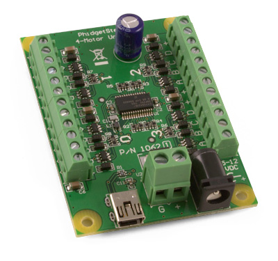
1062 User Guide
| |
| Go to this device's product page |
Getting Started
Checking the Contents
|
You should have received:
|
In order to test your new Phidget you will also need:
| |
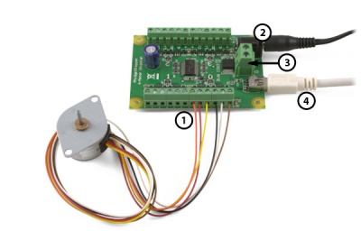
Connecting the Pieces
|
| |
Testing Using Windows 2000 / XP / Vista / 7
Make sure you have the current version of the Phidget library installed on your PC. If you don't, follow these steps:
- Go to the Quick Downloads section on the Windows page
- Download and run the Phidget21 Installer (32-bit, or 64-bit, depending on your system)
- You should see the
 icon on the right hand corner of the Task Bar.
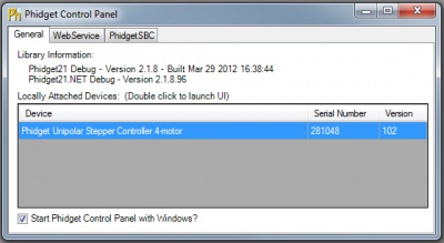
Running Phidgets Sample Program
Double clicking on the ![]() icon loads the Phidget Control Panel; we will use this program to ensure that your new Phidget works properly.
icon loads the Phidget Control Panel; we will use this program to ensure that your new Phidget works properly.
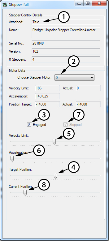
The source code for the Stepper-full sample program can be found in the quick downloads section on the C# Language Page. If you'd like to see examples in other languages, you can visit our Languages page.
Updating Device Firmware
If an entry in this list is red, it means the firmware for that device is out of date. Double click on the entry to be given the option of updating the firmware. If you choose not to update the firmware, you can still run the example for that device after refusing.
|
Double Click on the |
| |
|
|
Testing Using Mac OS X
- Go to the Quick Downloads section on the Mac OS X page
- Download and run the Phidget OS X Installer
- Click on System Preferences >> Phidgets (under Other) to activate the Preference Pane
- Make sure that the Phidget Unipolar Stepper Controller 4-motor is properly attached.
- Double Click on Phidget Unipolar Stepper Controller 4-motor in the Phidget Preference Pane to bring up the Stepper-full Sample program. This program will function in a similar way as the Windows version.
Using Linux
For a step-by-step guide on getting Phidgets running on Linux, check the Linux page.
Using Windows Mobile / CE 5.0 / CE 6.0
For a step-by-step guide on getting Phidgets running on Windows CE, check the Windows CE page.
Technical Details
How to Connect your Stepper to the 1062
Unipolar Stepper motors are available in 5, 6 or 8 wire configurations.
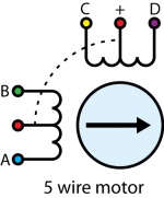
5 Wire Stepper Motors
|
In a 5 wire motor, the center taps of the coils are connected together. This scheme prevents this motor from being controlled as a bipolar motor. To use a 5 wire motor as a unipolar, the center tap wire is connected to the power supply. Determining how to connect a 5 wire stepper to a Unipolar Stepper Controller, like the 1062 can be done by following this procedure. Start by measuring the resistance between all the wires. Below is a sample table of resistance data, in ohms. This table contains example values, your readings may be different but should still produce a similar pattern. |
 | |
| Wire Color | Blue | Green | Red | Yellow | Purple |
|---|---|---|---|---|---|
| Blue | 147 | 74 | 147 | 147 | |
| Green | 74 | 147 | 147 | ||
| Red | 74 | 74 | |||
| Yellow | 147 | ||||
| Purple |
Looking at the table, you should notice a pattern; the red wire has the same resistance to the other four wires. This tells us that red is our + (center tap) wire, and should be wired to the power supply connection. On the 1062 PhidgetStepper, the power supply connection is labelled as (+). There are two power supply connections available on the 1062 for each motor - either can be used. Disconnect the power from the board and connect the center tap wire to the (+) connection.
Pick one of the remaining four wires and wire it to the A terminal, and connect the other wire for that coil to the B terminal. Connect the remaining wires to C and D. The motor should work regardless of which wire is connected to C and which is in D, but one of these combinations will result in a clockwise rotation for increasing position and counter-clockwise rotation for decreasing position, and the other will produce the opposite rotation.
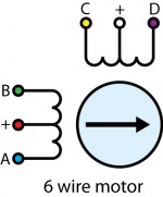
6 Wire Stepper Motors
|
The process is similar to a 5 wire motor. On a 6 – wire motor, there will be two + wires, one for each coil, which are the center taps for each coil. You will need to isolate which are the center tap wires and the corresponding wires for their coil. These center taps must be wired together to the power supply. Let’s assume our six wire stepper motor wires are colored as follows: red, green, black, white, brown, and yellow.
|
| |
| Wire Color | White | Red | Blue | Green | Purple | Yellow |
|---|---|---|---|---|---|---|
| White | ∞ | ∞ | ∞ | 10 | 10 | |
| Red | 10 | 10 | ∞ | ∞ | ||
| Blue | 20 | ∞ | ∞ | |||
| Green | ∞ | ∞ | ||||
| Purple | 20 | |||||
| Yellow |
Looking at our table, we can see our pattern. The white wire has the same resistance
to the purple and yellow wires. The red wire has the same resistance to the blue and
green wires. White, purple, and yellow bring out one coil, and red, blue, and green are the other coil. The red and
white wires are the center of their coils.
Disconnect the power from the board and connect the red and white wires to the (+) terminal block connections on the PhidgetStepper. Pick one of the remaining four wires and wire it to the A terminal, and connect the other wire for that coil to the B terminal. Connect the remaining wires to C and D. The motor should work regardless of which wire is connected to C and which is in D, but one of these combinations will result in a clockwise rotation for increasing position and counter-clockwise rotation for decreasing position, and the other will produce the opposite rotation.
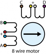
8 Wire Stepper Motors
|
8 Wire Motors are very difficult to wire up if you do not have a schematic showing how the wires are connected to the internal coils. Only follow these instructions if you are really desperate. In an 8 wire motor, the coils are split, and to operate it as a unipolar, we have to reconnect the coils to reduce it to a 6 wire unipolar. Assume our eight wire stepper motor wires are colored as follows: Orange, blue, red, green, brown, yellow, white and purple. In an 8-wire stepper motor, these wires would be part of 4 coils, 2 wires per coil. We need to determine the cable pairings. We measure the resistance between each wire and are presented with the following values in ohms (these are simply example values):
|
 | |
| Wire Color | Orange | Red | Yellow | Purple | Blue | Green | Brown | White |
|---|---|---|---|---|---|---|---|---|
| Orange | ∞ | ∞ | ∞ | 1 | ∞ | ∞ | ∞ | |
| Red | ∞ | ∞ | ∞ | 1 | ∞ | ∞ | ||
| Yellow | ∞ | ∞ | ∞ | 1 | ∞ | |||
| Purple | ∞ | ∞ | ∞ | 1 | ||||
| Blue | ∞ | ∞ | ∞ | |||||
| Green | ∞ | ∞ | ||||||
| Brown | ∞ | |||||||
| White |
This table tells us which wires are parts of a coil. From the table we can tell that orange/blue, green/red, brown/yellow, and white/purple are the coils.
Of each pair, one of the wires will be assigned to A, B, C, or D, and the other wire will be connected to another pair. The number of combinations to be tried to see if they produce rotation is large, but can be reduced to a maximum of 96 possibilities by following these steps:
- Choose Red/Blue to connect to A. (2 possibilities)
- Choose one wire of the other pairs (6 possibilities) and connect to B. The other wire from this pair is connected to the wire from Step 1 not connected to A.
- Choose one wire from the two remaining pairs (4 possibilities) and connect to C.
- Choose one wire from the remaining pair (2 possibilities) and connect to the wire from Step 3 not connected to C. The remaining wire from this pair is connected to D.
- After trying each permutation, engage the motor from software and try to rotate it. Since you are driving the motor as Unipolar, the connected pairs should be connected to the (+) on the PhidgetStepper Controller.
- If you attempt to use this algorithm, build a table of permutations beforehand and proceed in a systematic way.
There are a total of 96 wiring combinations, of which there are 2 valid combinations where one will cause a clockwise motor rotation and the other will cause a counter-clockwise rotation.
In order to properly determine the proper wiring for your motor we suggest consulting any manuals or data sheets that are associated with your particular motor.
Controlling Steppers
Stepper motors precision are limited by the manufacturing process used to build them. Errors in the rotor and coils will cause some degree of inaccuracy. In our experience, inexpensive stepper motors will often have positioning errors approaching a half-step.
Since stepper motors do not have the inherent ability to sense their actual shaft position, they are considered open loop systems. This means that the value contained in the current position property is merely a count of the number of steps that have occurred towards the target value; it can not be relied upon as a measure of the actual shaft angle, as the motor can occasionally understep or overstep due to forces such as inertia.
For many applications, it is acceptable for the motor to miss a few steps. In applications where positional accuracy is vital, there are several ways of overcoming this drawback. The simplest is to allow the motor load to depress a limit switch located at a known position. This can be used to fire an event in software to recalibrate the shaft position values. A more elegant solution might involve the mounting of an optical encoder on the shaft and the development of a control system.
Stepping Mechanism
The 1062 PhidgetStepper Unipolar controls stepper motors in half-step increments. A Position increment of one corresponds to one half-step. A stepper motor with 15 degree step increments will rotate in 7.5 degree steps. The 1062 accomplishes this by alternating the number of powered coils between one and two, always at least one coil powered. In this way, the rotor is positioned at both full steps and half steps. The table below describes the order in which coils are powered to achieve this.
| Step Number | Coil A | Coil B | Coil C | Coil D | Shaft Angle |
|---|---|---|---|---|---|
| 1 | ON | OFF | ON | OFF | 0º |
| 2 | ON | OFF | OFF | OFF | 7.5º |
| 3 | ON | OFF | OFF | ON | 15º |
| 4 | OFF | OFF | OFF | ON | 22.5º |
| 5 | OFF | ON | OFF | ON | 30º |
| 6 | OFF | ON | OFF | OFF | 37.5º |
| 7 | OFF | ON | ON | OFF | 45º |
| 8 | OFF | OFF | ON | OFF | 52.5º |
After step number 8 in the table, the order the coils are powered in simply repeats from the beginning. As the motor approaches the requested position, it is decelerated according to the value of the acceleration property. When the desired position has been reached, the 1062 stops the motor and holds it at that position.
Synchronization of Multiple Motors
Many applications call for several steppers motors operating in unison - for example, operating a CNC table, or a robot arm. Highly precise synchronization of steppers using the PhidgetStepper is not possible, as the sequencing will be affected by the real-time performance of your operating system. Each stepper is controlled as a independent unit, so there is no way of arranging for a particular action to happen to all motors at the same time. Typical jitter can be 10-30ms.
Compatibility Guidelines
When looking for a motor that will be compatible with the 1062, check the motor's data sheet and make sure it meets the following specifications.
- Unipolar motor - The 1062 can only be used with resistive-limited unipolar stepper motors.
- 5, 6, or 8-wire motor - A 4-wire motor cannot be used with the 1062, because the centre taps of the coils are not exposed.
- Rated/Recommended Voltage - If the motor comes with a rated or recommended voltage, it should be no more than 12 volts, and you should use a power supply that can output that voltage.
- Rated Current - The motor should be rated for a maximum of 1A per coil.
Further Reading
For more information about stepper motors and how they work, check the Stepper Motor and Controller Primer.
API
We document API Calls specific to this product in this section. Functions common to all Phidgets and functions not applicable to this device are not covered here. This section is deliberately generic. For calling conventions under a specific language, refer to the associated API manual in the Quick Downloads section for that language. For exact values, refer to the device specifications.
Functions
int MotorCount() [get]
- Returns the number of motors this PhidgetStepper can control. In the case of the 1062, this will always return 4. This call does not return the number of motors actually connected - on the 1062, there is no way of programmatically finding out if motors are connected.
double Acceleration(int MotorIndex) [get,set]
- Acceleration is the maximum change in velocity the PhidgetStepper uses when speeding up/ slowing down the motor. This is specified in the same units used for MotorPosition - in the case of the 1062, half-steps.
- If your motor is heavily loaded, or not supplied with a high enough voltage, there will be a practical limit on how fast it can accelerate.
- The range of valid Acceleration permitted is bounded by the software properties AccelerationMax/AccelerationMin.
- This property should be set by the user as part of initialization. If not set, this value will remain unknown, and could be any of: Minimum acceleration, mid-point acceleration, or any value previously set by another application.
double AccelerationMax(int MotorIndex) [get] : Constant
- AccelerationMax is the Maximum Acceleration the 1062 can accept, and apply to the motor. That does not mean that your motor can accelerate that fast! API for the PhidgetStepper Unipolar 4-Motor We document API Calls specific to this product in this section. Functions common to all Phidgets and functions not applicable to this device are not covered here. This section is deliberately generic. For calling conventions under a specific language, refer to the associated API manual. For exact values, refer to the device specifications.
double AccelerationMin(int MotorIndex) [get] : Constant
- AccelerationMin is the Minimum Acceleration the 1062 can accept, and apply to the motor.
double Velocity(int MotorIndex) [get]
- Velocity returns the current speed that a particular motor is being driven at. In the case of the 1062, the unit is half-steps per second. With the PhidgetStepper, there is no way of directly controlling the velocity of a motor, because of acceleration curves, however the maximum velocity (VelocityLimit) can be set. The Velocity is returned from the 1062 - so there will be a delay - typically 30-50ms.
double VelocityLimit(int MotorIndex) [get,set]
- Sets the maximum velocity that the stepper controller will move the motor. Please note that this is not necessarily the speed that the motor is being turned at. The motor is accelerated to the VelocityLimit, and then decelerated as it approaches the target. If the target is close enough, you may never reach the VelocityLimit.
- VelocityLimit is bounded by VelocityMax/VelocityMin.
- This property should be set by the user as part of initialization. If not set, this value will remain unknown, and could be any of: 0 (motor won’t move), mid-point velocity, or any value previously set by another application.
- Note that when VelocityLimit is set to 0, the motor will not move.
double VelocityMax(int MotorIndex) [get] : Constant
- VelocityMax is the Maximum VelocityLimit the 1062 can accept. Functionally, this is the maximum speed that the 1062 can drive your motors at.
double VelocityMin(int MotorIndex) [get] : Constant
- VelocityMin is the Minimum Velocity Limit the 1062 can accept.
int64 CurrentMotorPosition(int MotorIndex) [get,set]
- Returns the current position of a motor. Note that there will be some lag (typical 30-50ms) between the PhidgetStepper reporting a position, and that position being read by your application. CurrentMotorPosition is fixedpoint - an increment of one is one half-step - the smallest step that the 1062 can move the motor.
- Sets the current physical position of the motor to a specified current position value. For example, if you rotate the motor 180 degrees and then set current position to zero, the controller will treat this 180 degree position as the zero position. This function also sets the target position to the same value, in order to stop the motor from moving. This is useful for zeroing the position when a limit switch is reached. To keep accurate track of position, CurrentMotorPosition should only be set when the MotorStopped property is true, because if this property is set while the motor is moving, the motor will have to decelerate to stop moving, before setting the current position.
int64 TargetMotorPosition(int MotorIndex) [get,set]
- Sets the desired motor position. Note that setting TargetMotorPosition will override a previous set TargetMotorPosition, and the motor will begin tracking to the new position immediately. The velocity of the motor will be ramped appropriately. TargetMotorPosition is bounded by MotorPositionMin, and MotorPositionMax.
- Returns the last set TargetMotorPosition.
int64 MotorPositionMax(int MotorIndex) [get] : Constant
- MotorPositionMax is the Maximum MotorPosition the 1062 can accept. Functionally, this is the largest position that the 1062 can move your motors toward. The initial MotorPosition is halfway between Min and Max. Behaviour is undefined if MotorPosition is driven past Min or Max.
int64 MotorPositionMin(int MotorIndex) [get] : Constant
- MotorPositionMin is the Minimum MotorPosition the 1062 can move your motors toward.
bool Engaged(int MotorIndex) [get,set]
- Enables a particular stepper to be positioned. If this property is false, no power is applied to the motor. Note that when the motor is first Enabled, the coils may not be exactly aligned, and the motor will snap to position.MotorOn is useful to reduce the power consumed by a motor once it’s reached a given position. If you are concerned about keeping accurate track of position, MotorOn should not be disabled until MotorStopped = True.
bool Stopped(int MotorIndex) [get]
- MotorStopped guarantees that the motor is not moving (unless you are moving it by hand), and that there are no commands in the pipeline to the motor. Note that virtually any API calls will cause MotorStopped to be temporarily false, even changing Acceleration or VelocityLimit on a stopped motor.
Events
VelocityChange(int MotorIndex, double Velocity) [event]
- An event issued when the velocity changes on a motor.
PositionChange(int MotorIndex, int64 Velocity) [event]
- An event issued when the position changes on a motor. You are not guaranteed to receive events for every motor position - updates are throttled at approximately 16ms.
Product History
| Date | Board Revision | Device Version | Comment |
|---|---|---|---|
| April 2008 | 0 | 101 | Product Release |
| May 2011 | 0 | 102 | getLabelString fixed for lables > 7 characters |
| September 2011 | 1 | 102 | Replace USB Connector with Mini-USB connector. |