|
Notice: This page contains information for the legacy Phidget21 Library. Phidget21 is out of support. Bugfixes may be considered on a case by case basis. Phidget21 does not support VINT Phidgets, or new USB Phidgets released after 2020. We maintain a selection of legacy devices for sale that are supported in Phidget21. We recommend that new projects be developed against the Phidget22 Library.
|
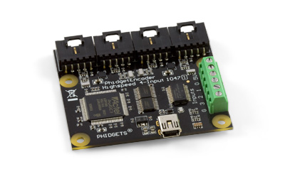
1047 User Guide
| |
| Go to this device's product page |
Getting Started
Checking the Contents
|
You should have received:
|
In order to test your new Phidget you will also need:
| |
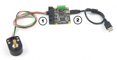
Connecting the Pieces
|
| |
Testing Using Windows 2000 / XP / Vista / 7
Make sure you have the current version of the Phidget library installed on your PC. If you don't, follow these steps:
- Go to the Quick Downloads section on the Windows page
- Download and run the Phidget21 Installer (32-bit, or 64-bit, depending on your system)
- You should see the
 icon on the right hand corner of the Task Bar.
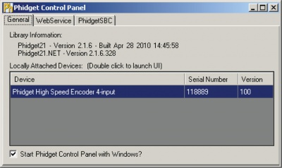
Running Phidgets Sample Program
Double clicking on the ![]() icon loads the Phidget Control Panel; we will use this program to ensure that your new Phidget works properly.
icon loads the Phidget Control Panel; we will use this program to ensure that your new Phidget works properly.
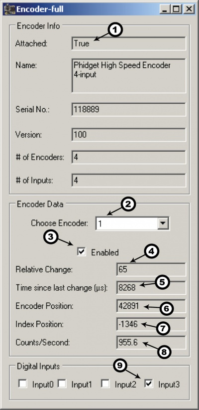
The source code for the Encoder-full sample program can be found in the quick downloads section on the C# Language Page. If you'd like to see examples in other languages, you can visit our Languages page.
Updating Device Firmware
If an entry in this list is red, it means the firmware for that device is out of date. Double click on the entry to be given the option of updating the firmware. If you choose not to update the firmware, you can still run the example for that device after refusing.
|
Double Click on the |
| |
|
|
Testing Using Mac OS X
- Go to the Quick Downloads section on the Mac OS X page
- Download and run the Phidget OS X Installer
- Click on System Preferences >> Phidgets (under Other) to activate the Preference Pane
- Make sure that the Phidget High Speed Encoder 4-Input is properly attached.
- Double Click on Phidget High Speed Encoder 4-Input in the Phidget Preference Pane to bring up the Encoder-full Sample program. This program will function in a similar way as the Windows version.
Using Linux
For a step-by-step guide on getting Phidgets running on Linux, check the Linux page.
Using Windows Mobile / CE 5.0 / CE 6.0
For a step-by-step guide on getting Phidgets running on Windows CE, check the Windows CE page.
Technical Details
The PhidgetEncoder Highspeed 4-Input can be used with a wide assortment of mechanical and optical encoders. The encoder should be of quadrature output type, indicating that there will be two quadrature output channels (usually labeled A and B) and a third output channel (only on some encoders) to signal when the index pin (a reference point for zero position or a complete revolution) has been reached.
The PhidgetEncoder Highspeed 4-Input is able to read four encoders simultaneously. Encoders are not powered up until all initialization of the device is complete. It is possible to enable some or all encoders, depending on how many of the channels are being used. This can also be used to reduce power consumption when certain encoders are not needed.
The PhidgetEncoder Highspeed 4-Input has the added ability to time the duration between a group of quadrature changes. The time is returned in microseconds. This time value can be used to calculate velocity and acceleration with very high precision.
If the number of quadrature counts per revolution is unknown for a particular encoder, this value can be determined by using the index signal. In addition, it is possible to monitor how many counts have occurred since the last index. The index signal is an output only on certain encoders. Refer to the encoder’s description to check if this third output channel exists or not. If the encoder does not have this signal, it is still possible to use it with the PhidgetEncoder Highspeed 4-Input, but an event for the index will never get triggered.
The maximum rate of the PhidgetEncoder Highspeed 4-Input is specified at 250,000 quadrature cycles per second. Since this device counts pulses rather than cycles, you could also say that it counts a maximum of 1,000,000 pulses per second (since there are four pulses in a cycle). In your application, these numbers relate directly to the number of revolutions per second you wish to measure, and the number of counts per revolution specified for your encoder. If your encoder's wheel has 1000 counts per revolution, then the limit on measurable revolutions per second is 250, or 15,000rpm (which, for the 1047, corresponds to 1000 position changes in software per second).
One of the most common problems encountered with connecting encoders to a 1047 is a strange "jitter" characterized by the encoder position appearing to switch back and forth between 0 and 1 or -1 and nothing else. This is usually indicative of a bad connection on either the A or B channel. You should check that the wiring is sound and try again.
Choosing Encoders
The PhidgetEncoder Highspeed 4-Input incorporates a 10 kOhm pull-up resistor on each line from the encoder input connector. If your encoder is mechanical, these pull-up resistors eliminate the requirement to add your own external pull-up resistors.
Some optical encoders will have a simple photo-transistor / open-collector output. The 10 kOhm pull-up resistor may have to be augmented with a stronger parallel resistor if your optical encoder datasheet calls for it. Some open-collector outputs will not be strong enough to pull this resistor to ground. These encoders are not compatible with the 1047, and may only work initially, or not at all. If you have any doubts, please contact us.
Most optical encoders have a push-pull output, and the pull-up resistor is irrelevant, but weak enough not cause problems.
We have reviewed the following encoders, and found that they can be used with the PhidgetEncoder Highspeed 4-Input. This is not meant to be a comprehensive list but should be used as examples of the type of encoders that can be used with the 1047.
| Manufacturer | Web Page | Part Number |
|---|---|---|
| Grayhill | www.Grayhill.com | Series 63R, Series 61R Series 63Q TTL Output |
| US Digital (Recommended) | www.USDigital.com | S4, S5, E2, E3, E4, E4P, etc. |
| Avago Technologies (Formerly Agilent) | www.avagotech.com | HEDS 5500 |
| CUI Inc. | www.cui.com | AMT103-V |
Connectors
Each Input uses a 5-pin, 0.100 inch pitch locking connector. The connectors are commonly available - refer to the Table below for manufacturer part numbers.
| Manufacturer | Part Number | Description |
|---|---|---|
| Molex | 50-57-9405 | 5 Position Cable Connector |
| Molex | 16-02-0102 | Wire Crimp Insert for Cable Connector |
| Molex | 70543-0004 | 5 Position Vertical PCB Connector |
| Molex | 70553-0004 | 5 Position Right-Angle PCB Connector (Gold) |
| Molex | 70553-0039 | 5 Position Right-Angle PCB Connector (Tin) |
| Molex | 15-91-2055 | 5 Position Right-Angle PCB Connector - Surface Mount |
Note: Most of the above components can be bought at Digikey.
Further Reading
If you want to know more about encoders, check out the Encoder Primer.
If you'd like to know more about the digital inputs on the 1047, visit the Digital Input Primer.
API
We document API Calls specific to this product in this section. Functions common to all Phidgets and functions not applicable to this device are not covered here. This section is deliberately generic. For calling conventions under a specific language, refer to the associated API manual in the Quick Downloads section for that language. For exact values, refer to the device specifications.
Functions
int InputCount() [get] : Constant
- Returns the number of digital inputs supported by this PhidgetEncoder. On the 1047, there are 4 digital inputs.
bool InputState (int EncoderIndex) [get]
- Returns the state of a particular digital input.
int EncoderCount() [get] : Constant
- Returns the number of encoders supported by this PhidgetEncoder Highspeed 4-Input. The 1047 supports up to four optical quadrature encoders.
int Position(int EncoderIndex) [get,set]
- Returns/sets the position of an encoder. This is an absolute position as calculated since the encoder was plugged in. Dividing position by the number of increments per revolution will give the number of rotations the encoder has travelled. Encoder position is returned in number of pulses, which is equivalent to four-times the number of encoder counts.
- Position can be set, typically used when an encoder has reached an identifiable (through external means, such as a limit switch) home position. This call does not send information to the device, as an absolute position is maintained only in the library. After this call, position changes from the encoder will use the new value to calculate absolute position.
int IndexPosition(int EncoderIndex) [get]
- Returns the index position of an enabled encoder. This will typically return the same value as Position(int EncoderIndex) except for on the event that an index has occurred, where it will return the exact position at which the encoder index was triggered.
bool Enabled(int EncoderIndex) [get,set]
- Returns true if the requested encoder is enabled; returns false if the requested encoder is disabled. Can be set true or false to decide whether the encoder is turned on or off. Disabled encoders will not draw power, detect position changes or trigger index events. Enabled encoders will draw power and trigger any requested events.
Events
OnPositionChange(int EncoderIndex, int Time, int PositionChange) [event]
- An event that is issued whenever a change in encoder position occurs on an enabled encoder. This event returns the length of time that the change took (in microseconds), and the amount of change (positive/negative encoder increments) for that particular encoder.
OnInputChange(int InputIndex, bool State) [event]
- An event that is issued whenever the state of a digital input changes.
C and .NET based APIs only:
OnIndexChange(int EncoderIndex, int IndexPosition) [event]
- An event that is issued whenever there is a pulse on the index pin. (Note: Many encoders do not support the index channel and leave the index pin unconnected)
Product History
| Date | Board Revision | Device Version | Comment |
|---|---|---|---|
| June 2010 | 0 | 100 | Product Release |
| May 2011 | 0 | 101 | getLabelString fixed for labels of length >7 |
| January 2012 | 0 | 102 | Fixed initial power state of channels 3 and 4 |
| June 2012 | 1 | 102 | Replaced power switches for added stability |
| March 2015 | 1 | 103 | Fixed a timing bug |