|
Notice: This page contains information for the legacy Phidget21 Library. Phidget21 is out of support. Bugfixes may be considered on a case by case basis. Phidget21 does not support VINT Phidgets, or new USB Phidgets released after 2020. We maintain a selection of legacy devices for sale that are supported in Phidget21. We recommend that new projects be developed against the Phidget22 Library.
|
1044 User Guide
| |
| Go to this device's product page |
Getting Started
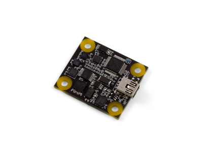
Checking the Contents
|
You should have received:
|
||
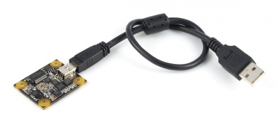
Connecting the Pieces
|
Connect the PhidgetSpatial 3/3/3 to your PC using the Mini-B USB cable. |
| |
Testing Using Windows 2000 / XP / Vista / 7
Make sure you have the current version of the Phidget library installed on your PC. If you don't, follow these steps:
- Go to the Quick Downloads section on the Windows page
- Download and run the Phidget21 Installer (32-bit, or 64-bit, depending on your system)
- You should see the
 icon on the right hand corner of the Task Bar.
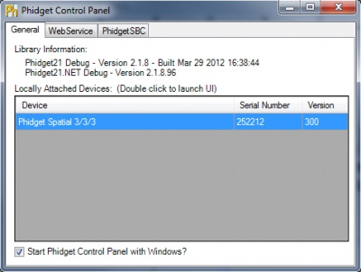
Running Phidgets Sample Program
Double clicking on the ![]() icon loads the Phidget Control Panel; we will use this program to ensure that your new Phidget works properly.
icon loads the Phidget Control Panel; we will use this program to ensure that your new Phidget works properly.
The source code for the Spatial-full sample program can be found in the quick downloads section on the C# Language Page. If you'd like to see examples in other languages, you can visit our Languages page.
Updating Device Firmware
If an entry in this list is red, it means the firmware for that device is out of date. Double click on the entry to be given the option of updating the firmware. If you choose not to update the firmware, you can still run the example for that device after refusing.
|
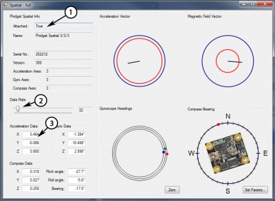
Double Click on the |
| |
|
|
Testing Using Mac OS X
- Go to the Quick Downloads section on the Mac OS X page
- Download and run the Phidget OS X Installer
- Click on System Preferences >> Phidgets (under Other) to activate the Preference Pane
- Make sure that the Phidget Spatial 3/3/3 is properly attached.
- Double Click on Phidget Spatial 3/3/3 in the Phidget Preference Pane to bring up the Spatial-full Sample program. This program will function in a similar way as the Windows version.
Using Linux
For a step-by-step guide on getting Phidgets running on Linux, check the Linux page.
Using Windows Mobile / CE 5.0 / CE 6.0
For a step-by-step guide on getting Phidgets running on Windows CE, check the Windows CE page.
Technical Details
High Resolution Mode
When the PhidgetSpatial High Resolution 3/3/3 measures an acceleration value with magnitude less than 2g, it will acquire its data from a higher precision accelerometer chip. For these measurements, the average white noise on each axis will be reduced by approximately a factor of ten, and the resolution will increase from 976 μg to 76 μg. Likewise, when the gyroscope measures a rotation value with magnitude less than 300 °/s on the Z-axis or 400 °/s on the X or Y-axis, the noise per axis will be approximately six times lower, and the resolution will increase from 0.07 °/s to 0.02 °/s. The transition from normal to high precision or vice-versa is seamless, with no additional code or equations needed.
3-Axis Accelerometer
The PhidgetSpatial 3/3/3 has a 3-Axis accelerometer that can measure ±8 g (±78 m/s2) per axis. It will measure both dynamic acceleration (change in velocity) and static acceleration (gravity vector).
For more information on how to use the accelerometer, check the Accelerometer Primer.
3-Axis Gyroscope
For more information on the gyroscope, see the Gyroscope Primer.
3-Axis Magnetometer (Compass)
The magnetometer reports the sum of all magnetic fields acting on the 1044 device. The earth’s magnetic field is only one source that affects this measurement. In order to get accurate bearing data from the magnetometer - ie. to find magnetic north as a compass - any interfering magnetic effects need to be calibrated out. For more information about calibration, see the section below, or the Compass Primer.
Any magnetic field that is stationary with respect to the 1044 device, and less than ± 3 Gauss, can be calibrated out of the magnetic field measurement. This includes both hard and soft iron effects caused by nearby ferrous and magnetic materials. Interfering magnetic fields that vary in strength and orientation with respect to the 1044 device cannot be easily calibrated out.
Magnetic field data will become unavailable during every other sample as the compass performs internal calibrations. When this happens, the magneticField array in the SpatialData structure will either have a length of zero, or each element will equal PUNK_DBL, depending on the API being used. This needs to be handled explicitly in the event handling code to avoid erroneous program behavior. The maximum sampling rate of the compass is 125 Hz.
Magnetic Error Correction (Calibration)
In order to get numbers of useful accuracy from the 1044's compass you will need to provide calibration parameters. To make determining them easy, we distribute a program with our drivers that does this for you.
To calibrate your compass:
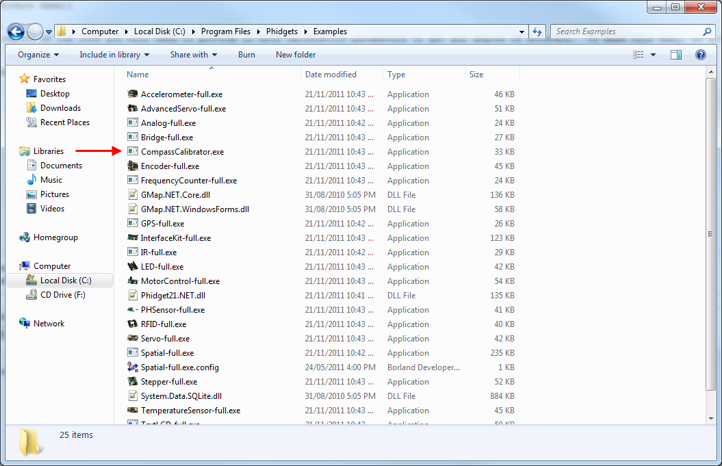
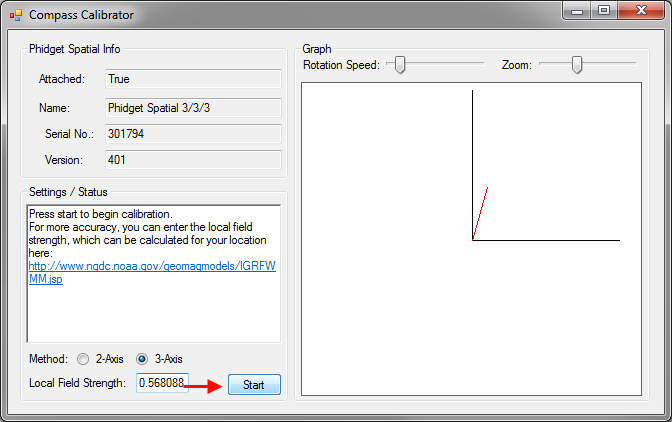
- Navigate to the Phidgets installation folder on your computer. Open the 'examples' folder and find the Compass Calibrator program.
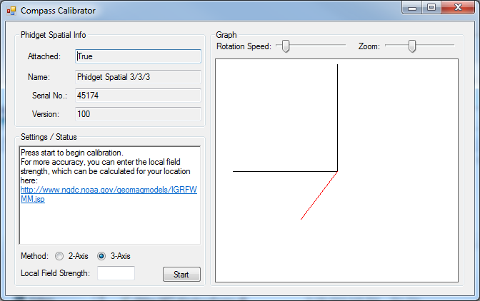
- Start the program and find the link in the Settings/Status text box. Go to the website listed. (http://www.ngdc.noaa.gov/geomag-web/#igrfwmm)
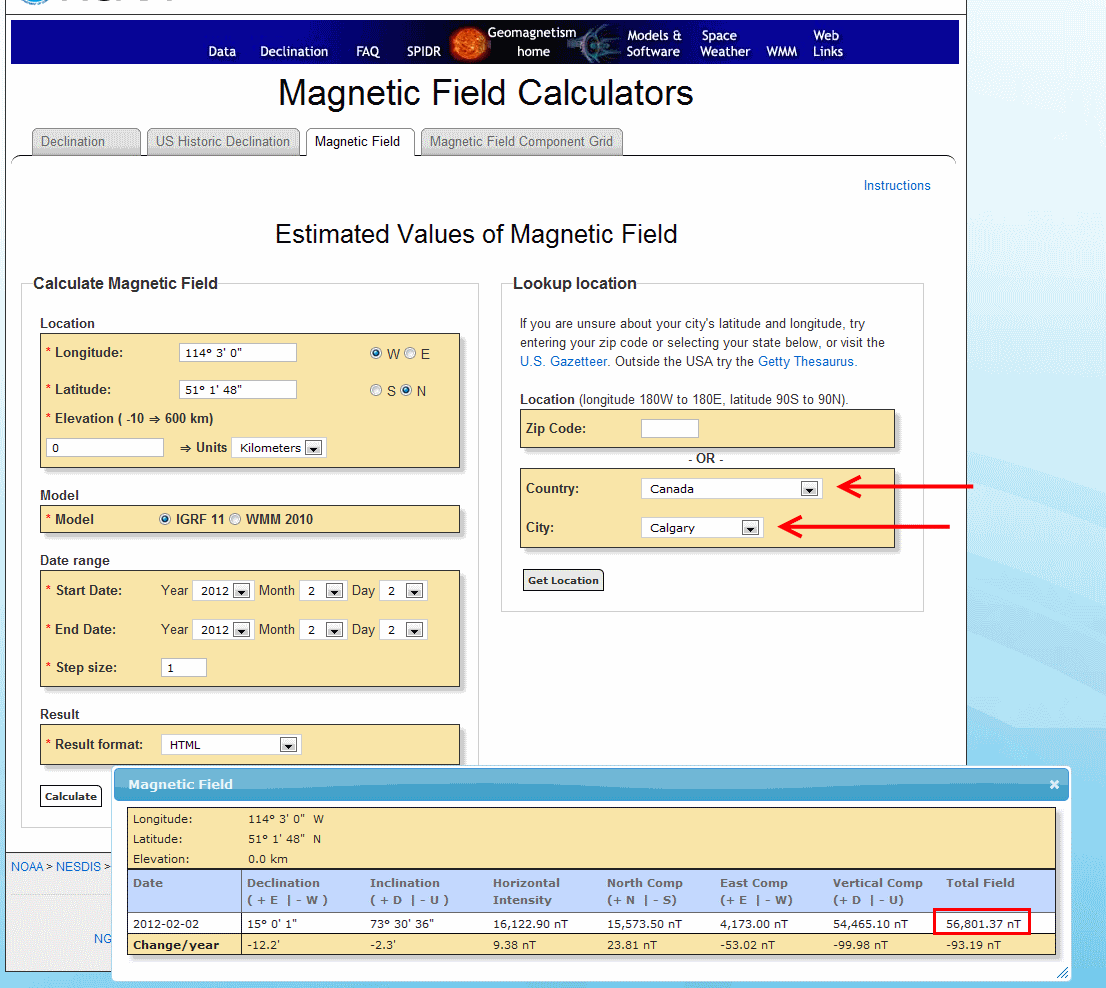
- Select your country and city. Click 'Get Location' and then 'Compute'. A table of values will show up in an overlaid window. The value you will need is the 'Total Field' value in nT.
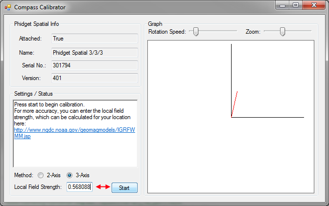
- Enter the magnetic field value into the calibration program. Note that it wants the field strength in Gauss, not nT like the website gives you. 1T = 10000 Gauss so you can divide by 1x10^5 to convert to Gauss.
- Depending on what your application is this step as well as the next step might be a bit different. If you are intending on mounting the 1044 onto a large vehicle such as a car then you should mount the 1056 securely to the vehicle in its final intended position then check the 2-axis bubble, click the 'Start' button.
- If you are using a smaller, more easily handled vehicle such as a small robot (something you could physically pick up) you will mount the 1044 and use the 3-axis calibration instead. Click 'Start'.
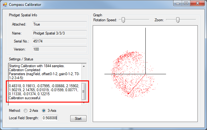
- Rotate the compass around (including whatever equipment you have mounted it to) such that the red dots being generated on screen outline as much of a full sphere (in 3-axis) as possible. This will take several minutes. Being perfect is not necessary but try to be as thorough as time permits. Once done, click stop.
- If you are in a large vehicle, you will be aiming to fill out a disc instead of a sphere. This can be done by simply driving around for a few minutes making sure to do complete turns in the process.

- Take the parameters displayed in the text box and use them for your compass. For example in C#:
setCompassCorrectionParameters(0.51075, 0.18820, -0.07456, -0.02209, 1.87163, 1.87640, 2.12565, -0.04000, -0.04084, -0.03552, 0.09073, -0.04258, 0.11056);
For more information on magnetometers (compasses), see the Compass Primer.
API
We document API Calls specific to this product in this section. Functions common to all Phidgets and functions not applicable to this device are not covered here. This section is deliberately generic. For calling conventions under a specific language, refer to the associated API manual in the Quick Downloads section for that language. For exact values, refer to the device specifications.
Data Structures
SpatialData {
- double acceleration[3];
- double angularRate[3];
- double magneticField[3];
- Timestamp time;
};
Timestamp {
- int seconds; -time since attach event
- int microseconds; -time since last second
};
The SpatialData Structure is used by the OnSpatialData event. This contains acceleration data, angular rate data, magnetic field data, and a timestamp. The timestamp is an accurate measurement streamed from the hardware,and can be trusted over a local software timestamp. This timestamp is generally used for integrating angular rate into a heading over time.
Properties
int AccelerationAxisCount() [get] : Constant = 3
- Returns the number of axes the PhidgetSpatial can measure acceleration on.
double Acceleration (int AxisIndex) [get] : Units = g (standard gravity = 9.81m/s2)
- Returns the acceleration of an axis. At a standstill each axis will measure between -1.0 and 1.0 g’s depending on orientation - the effect of gravity.
This value will always be between AccelerationMin and AccelerationMax.
double AccelerationMax (int AxisIndex) [get] : Constant = 8.1g
- Returns the maximum acceleration value that this axis will report. Acceleration can be accurately measured up to 8.0g - any value past this will be reported as 8.1g, which represents saturation. If the acceleration data is equal to AccelerationMax, it should be treated as suspect, as the real acceleration could be far greater than the reported number.
double AccelerationMin (int AxisIndex) [get] : Constant = -8.1g
- Returns the maximum negative acceleration value that this axis will report. Negative acceleration can be accurately measured up to -8.0g - any value past this will be reported as -8.1g, which represents saturation. If the acceleration data is equal to AccelerationMin, it should be treated as suspect, as the real acceleration could be far greater than the reported number.
int GyroAxisCount() [get] : Constant = 3
- Returns the number of axes the PhidgetSpatial can measure angular momentum on.
int AngularRate(int AxisIndex) [get] : Units = °/s (degrees/second)
- Returns the angular momentum on an axis. This value will always be between AngularRateMax and AngularRateMin. If the value is equal to AngularRateMax or Min, the data should be treated as suspect, as the sensor may be saturated.
int AngularRateMax(int AxisIndex) [get] : Constant = 2000°/s
- Returns the maximum angular momentum that this axis will report. If the angular rate is reported as 2000°/s, this should be considered saturated, and any heading integration will have errors.
int AngularRateMin(int AxisIndex) [get] : Constant = -2000°/s
- Returns the maximum negative angular momentum that this axis will report. If the angular rate is reported as -2000°/s, this should be considered saturated, and any heading integration will have errors.
int CompassAxisCount() [get] : Constant = 3
- Returns the number of axes the PhidgetSpatial can measure magnetic field strength on.
int MagneticField(int AxisIndex) [get] : Units = G (gauss)
- Returns the magnetic field on an axis. This value will always be between MagneticFieldMax and MagneticFieldMin. If the reported value is equal to MagneticFieldMax or Min, the data should be treated as suspect, as the sensor may be saturated. Magnetic field measurements can be combined to calculate compass bearing (magnetic north).
If your data rate is set to 4ms (the default is 8ms), Magnetic field data will become unavailable for every other sample. When this happens, this function will return EPHIDGET_UNKNOWNVAL, or throw an UNKNOWNVAL exception, depending on the API being used. Also, the magneticField array in the SpatialData structure will either have a length of zero, or each element will equal PUNK_DBL, depending on the API being used. This needs to be handled explicitly in the event handling code to avoid erroneous program behavior when using a sampling rate of 4ms.
int MagneticFieldMax(int AxisIndex) [get] : Constant = 5.6G
- Returns the maximum magnetic field that this axis will report. Magnetic field strength can be accurately measured up to 5.5G - any value past this will be reported as 5.6G, which represents saturation. If the magnetic field data is equal to MagneticFieldMax, it should be treated as suspect, as the real magnetic field could be far greater than the reported number.
int MagneticFieldMin(int AxisIndex) [get] : Constant = -5.6G
- Returns the maximum negative magnetic field that this axis will report. Magnetic field strength can be accurately measured down to -5.5G - any value past this will be reported as -5.6G, which represents saturation. If the magnetic field data is equal to MagneticFieldMin, it should be treated as suspect, as the real magnetic field could be far greater than the reported number.
int DataRate () [get,set] : Units = ms (milliseconds)
- Gets/sets the data rate. This is corresponds to the time interval at which SpatialData events will be fired. This is bound by DataRateMax and DataRateMin. When set to less then the maximum data rate, data is still sampled at the maximum rate, and averaged before being sent to the user.
Supported data rates are: 4ms and every multiple of 4 up to 1000ms (ie. 8, 12, 16, 20, etc). The default data rate is 8ms. Data rate is limited to at most 16ms when opening over the Phidget Webservice. Actual data rate will depend on network latency.
int DataRateMax () [get] : Constant = 4ms
- The maximum supported data rate.
int DataRateMin () [get] : Constant = 1000ms
- The minimum supported data rate.
Functions
void setCompassCorrectionParameters(double magField, double offset0, double offset1, double offset2, double gain0, double gain1, double gain2, double T0, double T1, double T2, double T3, double T4, double T5);
- Sets correction parameters for the magnetometer. This can be used to correct for hard and soft iron offsets, bias errors in the magnetometer, etc. The parameters are determined by the Compass Calibrator application included in the driver package. The calibrator will also load the parameters onto the compass making this function generally not useful outside of specific corner cases where you want to adjust the parameters on the fly (you shouldn't do this normally).
Parameters:
- magField: The reference field to use. Generally, use the local expected field strength, or 1.0.
- offset0,1,2: Applies offset to the compass data in axes 0,1,2.
- gain0,1,2: Applies gain corrections in axes 0,1,2.
- T0,1,2,3,4,5: Applies corrections for non-orthogonality of the ellipsoid.
void zeroGyro();
- Re-zeroes the gyroscope. This takes 1-2 seconds of gyro samples and uses this data as a new zero point. The 1044 must remain stationary during the zeroing process. The angular rate will be reported as zero during zeroing.
Events
OnSpatialData (SpatialData[] data) [event]
- An event issued at the specified data rate. If the data rate is set faster then 8ms, then there will be multiple items in the data array - use the timestamp field to get the timing data. When the data rate is >= 8ms, there will only beone item in the data array.
If your data rate is set to 4ms (the default is 8ms), Magnetic field data will become unavailable for every other sample. When this happens, this function will return EPHIDGET_UNKNOWNVAL, or throw an UNKNOWNVAL exception, depending on the API being used. Also, the magneticField array in the SpatialData structure will either have a length of zero, or each element will equal PUNK_DBL, depending on the API being used. This needs to be handled explicitly in the event handling code to avoid erroneous program behavior when using a sampling rate of 4ms.
Product History
| Date | Board Revision | Device Version | Comment |
|---|---|---|---|
| September 2012 | 0 | 400 | Product Release |
| September 2012 | 0 | 401 | Fixed USB bug |
| October 2015 | 0 | 402 | OS X El Capitan USB Fix |