|
Notice: This page contains information for the legacy Phidget21 Library. Phidget21 is out of support. Bugfixes may be considered on a case by case basis. Phidget21 does not support VINT Phidgets, or new USB Phidgets released after 2020. We maintain a selection of legacy devices for sale that are supported in Phidget21. We recommend that new projects be developed against the Phidget22 Library.
|
1023 User Guide
| |
| Go to this device's product page |
Getting Started
Checking the Contents
|
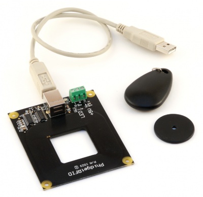
You should have received:
|
In order to test your new Phidget you will also need:
| |
Connecting the Pieces
|
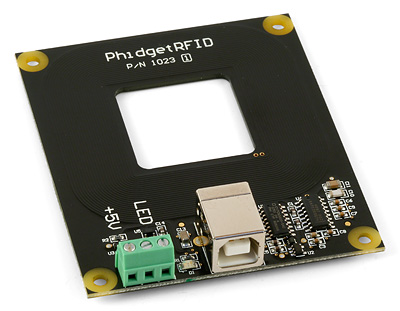
Connect the PhidgetRFID board to the computer using the USB cable. |
| |
Testing Using Windows 2000 / XP / Vista / 7
Make sure you have the current version of the Phidget library installed on your PC. If you don't, follow these steps:
- Go to the Quick Downloads section on the Windows page
- Download and run the Phidget21 Installer (32-bit, or 64-bit, depending on your system)
- You should see the
 icon on the right hand corner of the Task Bar.
Running Phidgets Sample Program
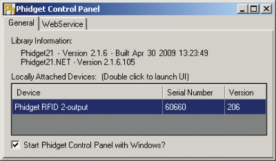
Double clicking on the ![]() icon loads the Phidget Control Panel; we will use this program to ensure that your new Phidget works properly.
icon loads the Phidget Control Panel; we will use this program to ensure that your new Phidget works properly.
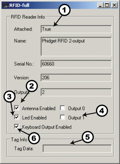
The source code for the PhidgetRFID-Full sample program can be found in the quick downloads section on the C# Language Page. If you'd like to see examples in other languages, you can visit our Languages page.
Updating Device Firmware
If an entry in this list is red, it means the firmware for that device is out of date. Double click on the entry to be given the option of updating the firmware. If you choose not to update the firmware, you can still run the example for that device after refusing.
|
Double Click on the |
| |
|
|
Testing Using Mac OS X
- Go to the Quick Downloads section on the Mac OS X page
- Download and run the Phidget OS X Installer
- Click on System Preferences >> Phidgets (under Other) to activate the Preference Pane
- Make sure that the Phidget RFID is properly attached.
- Double Click on Phidget RFID in the Phidget Preference Pane to bring up the RFID-full Sample program. This program will function in a similar way as the Windows version.
Using Linux
For a step-by-step guide on getting Phidgets running on Linux, check the Linux page.
Using Windows Mobile / CE 5.0 / CE 6.0
For a step-by-step guide on getting Phidgets running on Windows CE, check the Windows CE page.
Technical Details
Controlled Outputs
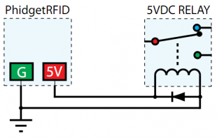
The PhidgetRFID has four outputs - two of which are available to the user, and two of which are for internal control of the Phidget board only. Output 0 is a +5V source from the USB bus through a P-Channel MOSFET with less than one ohm impedance. This can be used to switch a TTL or CMOS device, or it can be used to drive a 5VDC relay such as the Aromat JS1-5V. Output 1 is an LED drive output at 5VDC with maximum 15mA of available current (250 ohm CMOS output). Both Output 0 and 1 are available in hardware at the terminal blocks on the PhidgetRFID board. If Output 0 is used to drive a relay, a fast clamping diode must be placed across the relay drive pins as shown in the diagram on the right. Not doing so can result in permanent damage to the PhidgetRFID board.
| Output | Function | Connection |
|---|---|---|
| 0 | +5VDC Source | Terminal Block |
| 1 | External LED Drive | Terminal Block |
| LED | Internal LED Drive | Internal Only |
| RF Enable | RF Antenna Enable | Internal Only |
Interfering Signals
If you are using multiple RFID readers, placing them too close together will cause interference when reading tags. You could work around this problem by rapidly "polling" each 1023 by turning the antenna on, checking for tags, and then turning it off in sequence. Of course, this will lengthen the amount of time it takes for your system to read a tag, since you may have to wait for the nearest reader to become active.
Object Speed
When trying to read tags, you should allow the tag to remain within detection range for at least 50ms. Tags moving through the detection area faster than this may not register at all.
Further Reading
For more information on RFID readers and tags, visit the RFID Primer.
API
We document API Calls specific to this product in this section. Functions common to all Phidgets and functions not applicable to this device are not covered here. This section is deliberately generic. For calling conventions under a specific language, refer to the associated API manual in the Quick Downloads section for that language. For exact values, refer to the device specifications.
Functions
int OutputCount () [get] : Constant
- Returns the number of digital outputs available on this PhidgetRFID. These are the outputs provided by the terminal block.
bool OutputState (int OutputIndex) [get,set]
- Sets/Returns the state of an output. True indicates activated, False deactivated. False is the default state.
bool AntennaOn() [get,set]
- Sets/Returns the state of the antenna. True turns the antenna on, False turns it off. The antenna if by default turned off, and needs to be explicitely activated before tags can be read.
bool LEDOn() [get,set]
- Sets/Returns the state of the onboard LED. True turns the LED on, False turns it off. The LED is by default turned off.
string LastTag () [get]
- Returns the last tag read. This method will only return a valid tag after a tag has been seen. This method can be used even after a tag has been removed from range of the reader.
bool TagStatus() [get]
- Returns the state of whether or not a tag is being read by the reader. True indicates that a tag is on (or near) the reader.
Events
OnOutputChange(int OutputIndex, bool State) [event]
- An event issued when an output has changed.
OnTag(string) [event]
- An event issued when a new tag is seen by the reader. The event is only fired one time for a new tag, so the tag has to be removed and then replaced before another OnTag event will fire.
Note: it is very important not to block in this event, or you will receive extra attach / detach events.
OnTagLost(string) [event]
- An event issued when a tag is removed from the reader.
Product History
| Date | Board Revision | Device Version | Comment |
|---|---|---|---|
| June 2002 | 0 | 103 | Product Release |
| April 2004 | 0 | 200 | Onboard LED, 2 Digital Outputs added. Ability to enable/disable Antenna added. |
| January 2005 | 0 | 201 | RF Circuitry upgraded to improve reliability |
| January 2006 | 0 | 202 | Onboard microprocessor upgraded to Flash version. |
| September 2006 | 0 | 203 | Changed enable functionality to re-initialize reader |
| June 2006 | 0 | 204 | Low Voltage Reset set at 4.7 Volts |
| April 2007 | 0 | 205 | Protocol parsing bug fixed which garbled top 3 bits of RFID Tag. |
| July 2007 | 1 | 206 | Unused internal I/O pulled high out of an abundance of caution, bus current characterized. Terminal block moved to edge of PCB, center of antenna routed out, digital output transients on startup eliminated. |
| June 2013 | Product Discontinued. Succeeded by the 1024 - PhidgetRFID Read/Write. The 1024 differs from the 1023 in its ability to write to tags with the T5577 chipset, and to read tags belonging to a number of additional protocols. | ||