|
Notice: This page contains information for the legacy Phidget21 Library. Phidget21 is out of support. Bugfixes may be considered on a case by case basis. Phidget21 does not support VINT Phidgets, or new USB Phidgets released after 2020. We maintain a selection of legacy devices for sale that are supported in Phidget21. We recommend that new projects be developed against the Phidget22 Library.
|
1010 User Guide
| |
| Go to this device's product page |
Getting Started
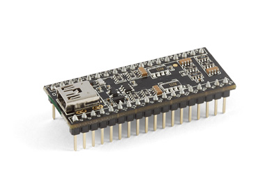
In order to use the 1010, you must be comfortable with designing your own circuit. You will need to understand the “signals” coming from and going to the 1010.
If you are not familiar with Phidgets, we recommend purchasing a 1018 to familiarize yourself with Phidget concepts before attempting to design the 1010 into your system.
Here is an example of a small board we have built for internal testing purposes. We have some LEDs, 2 relays, a power jack, and a couple of connectors.
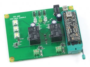
The schematic for this board is available here:
Technical Details
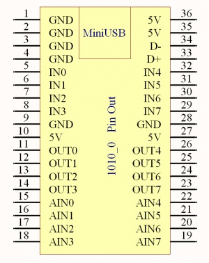
5V is the USB Power Supply - made available to your application if it requires a small amount of current (<400mA). All 5V pins are connected together internally.
GND is the USB Ground - all ground pins are connected together internally.
D+ and D- are the differential USB data lines.
IN0 - IN7 are digital inputs. For more information, see the Digital Input Primer.
OUT0 - OUT7 are digital outputs. For more information, see the Digital Output Primer.
AIN0 - AIN7 are analog inputs. For more information, see the Analog Input Primer.
For dimensions, please refer to the Mechanical Drawing on the Product Page.
API
We document API Calls specific to this product in this section. Functions common to all Phidgets and functions not applicable to this device are not covered here. This section is deliberately generic. For calling conventions under a specific language, refer to the associated API manual in the Quick Downloads section for that language. For exact values, refer to the device specifications.
Functions
int InputCount() [get] : Constant = 8
- Returns the number of digital inputs supported by this PhidgetInterfaceKit.
bool InputState(int InputIndex) [get]
- Returns the state of a particular digital input. Digital inputs read True where they are activated and false when they are in their default state.
int OutputCount() [get] : Constant = 8
- Returns the number of digital outputs supported by this PhidgetInterfaceKit.
bool OutputState (int OutputIndex) [get,set]
- Sets/returns the state of a digital output. Setting this to true will activate the output, False is the default state. Reading the OutputState immediately after setting it will not return the value set - it will return the last state reported by the Phidget.
int SensorCount() [get] : Constant = 8
- Returns the number of sensors (Analog Inputs) supported by this PhidgetInterfaceKit. Note that there is no way of determining is a sensor is attached, and what sensor is attached.
int SensorValue(int SensorIndex) [get]
- Returns the sensed value of a particular Analog Input. SensorValue varies between 0-1000, corresponding to the 0-5V input range of the Analog Input. If you are using an Analog Sensor from Phidgets Inc., it’s manual will specify the formula used to convert SensorValue into the measured property.
int SensorRawValue (int SensorIndex) [get]
- Returns the full resolution of the Analog Input. This is a more accurate version of SensorValue. The valid range is 0-4095. Note however that the analog outputs on the Interface Kit 8/8/8 are only 10-bit values and this value represents an oversampling to 12-bit.
double SensorChangeTrigger (int SensorIndex) [get,set]
- Returns the change trigger for an analog input. This is the amount that an inputs must change between successive SensorChangeEvents. This is based on the 0-1000 range provided by getSensorValue. This value is by default set to 10 for most Interface Kits with analog inputs. SensorChangeTrigger is sometimes referred to as sensitivity.
int DataRate (int SensorIndex) [get,set]
- Gets/sets the data rate for an analog input. This is corresponds to the fastest rate at which SensorChange events will be fired. The data rate is superseded by SensorChangeTrigger, which can be set to 0 if a constant data rate is required. Data Rate is in milliseconds and corresponds to the amount of time between events. Data Rate is bounded by DataRateMax and DataRateMin. The analog inputs cannot all be set to the fastest data rate at the same time - if this is attempted, an exception will be thrown when the data bandwidth has been exceeded. For data rates less then the maximum, data is still sampled at the maximum speed, and averaged between events for the user. Supported data rates are: 1, 2, 4, 8, and every multiple of 8 until DataRateMin. Setting an unsupported data rate (ie. 3, 9, 17) will result in a thrown exception. Note that data rate is limited to 16ms when opening over the Phidget Webservice.
int DataRateMax (int SensorIndex) [get]
- The maximum data rate that can be set for an analog input, in milliseconds.
int DataRateMin (int SensorIndex) [get]
- The minimum data rate that can be set for an analog input, in milliseconds. This is usually 1000.
bool Ratiometric() [get,set]
- Sets/returns the state of Ratiometric. Ratiometric = true configures the Analog Inputs to measure with respect to VCC (nominal 5V). Ratiometric = false configures the Analog Inputs to measure with respect to an internal precision 5V reference. Ratiometric is not updated from the Phidget. It is recommended to explicitly set Ratiometric when the Interfacekit is opened. After changing the ratiometric state, wait until the ratiometric property matches what was set before reading analog data.
Events
OnInputChange(int InputIndex, bool State) [event]
- An event that is issued when the state of a digital input changes.
OnOutputChange(int OutputIndex, bool State), [event]
- An event that is issued when the state of a digital output changes.
OnSensorChange(int SensorIndex, int SensorValue), [event]
- An event that is issued when the returned value from a sensor (Analog Input) varies by more than the SensorChangeTrigger property.
Product History
| Date | Board Revision | Device Version | Comment |
|---|---|---|---|
| April 2011 | 0 | 903 | Product Release |
| May 2011 | 0 | 904 | getLabelString fix for lables > 7 characters |