RCC1000 User Guide
Part 1: Setup
Welcome to the RCC1000 user guide! In order to get started, make sure you have the following hardware on hand:
- RCC1000 - 16x Servo Phidget
- VINT Hub
- Phidget Cable
- 8-30V Power supply
- Servo Motors
Next, you will need to connect the pieces:
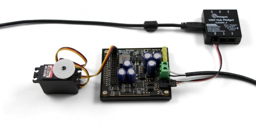
- Connect the RCC1000 to the VINT Hub using the Phidget cable.
- Connect the VINT Hub to your computer with a USB cable.
- Connect one or more servo motors to the RCC1000.
- Connect the power supply to the green power terminals on the RCC1000.
Now that you have everything together, let's start using the RCC1000!
Phidget Control Panel
In order to demonstrate the functionality of the RCC1000, the Phidget Control Panel running on a Windows machine will be used.
The Phidget Control Panel is available for use on both macOS and Windows machines.
Windows
To open the Phidget Control Panel on Windows, find the ![]() icon in the taskbar. If it is not there, open up the start menu and search for Phidget Control Panel
icon in the taskbar. If it is not there, open up the start menu and search for Phidget Control Panel
macOS
To open the Phidget Control Panel on macOS, open Finder and navigate to the Phidget Control Panel in the Applications list. Double click on the ![]() icon to bring up the Phidget Control Panel.
icon to bring up the Phidget Control Panel.
For more information, take a look at the getting started guide for your operating system:
Linux users can follow the getting started with Linux guide and continue reading here for more information about the RCC1000.
First Look
After plugging the RCC1000 into your computer and opening the Phidget Control Panel, you will see something like this:
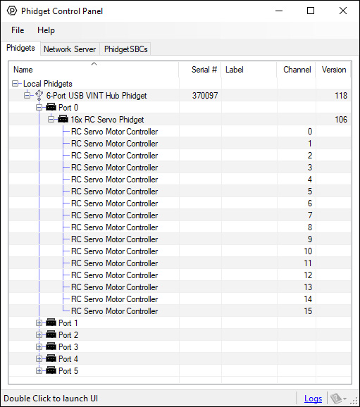
The Phidget Control Panel will list all connected Phidgets and associated objects, as well as the following information:
- Serial number: allows you to differentiate between similar Phidgets.
- Channel: allows you to differentiate between similar objects on a Phidget.
- Version number: corresponds to the firmware version your Phidget is running. If your Phidget is listed in red, your firmware is out of date. Update the firmware by double-clicking the entry.
The Phidget Control Panel can also be used to test your device. Double-clicking on an object will open an example.
Part 2: Using Your Phidget
About
The RC Servo Phidget can control the position, velocity, and acceleration of up to 16 RC servo motors. It is powered externally by an 8-30V supply, providing a total of up to 20A of regulated power to its servos. You can control the regulator and choose a global voltage of 5.0V, 6.0V, or 7.4V. A servo will have more torque when running at a higher voltage but will have a shorter overall lifespan.
Explore Your Phidget Channels Using The Control Panel
You can use your Control Panel to explore your Phidget's channels.
1. Open your Control Panel, and you will find the following channels:
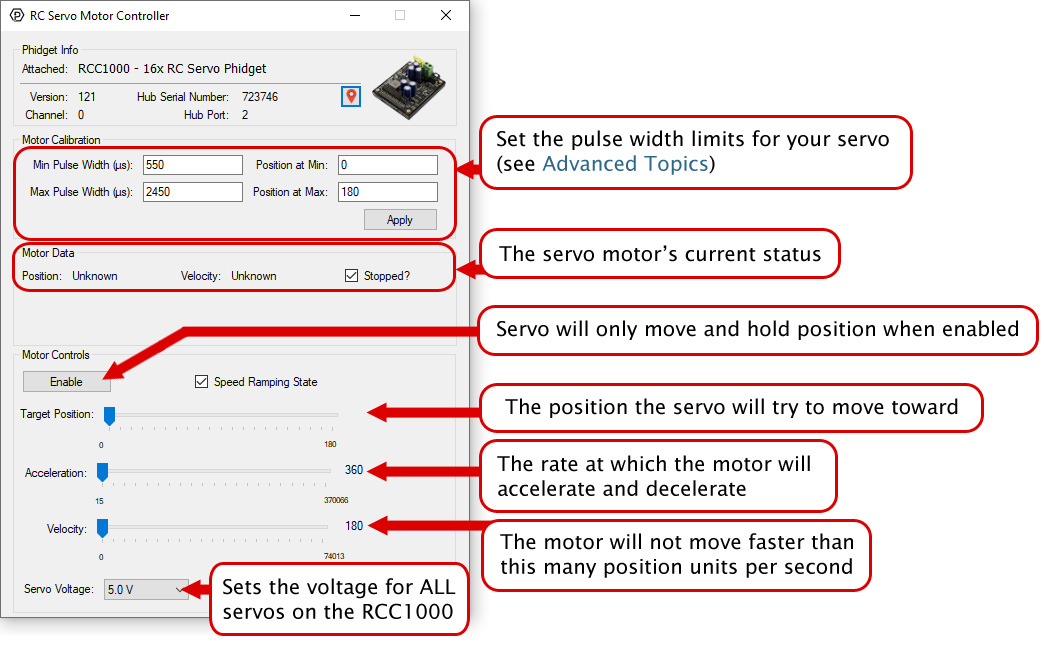
2. Double click on a channel to open an example program. Each channel belongs to the RCServo channel class:
In your Control Panel, double click on "RC Servo Motor Controller":
Part 3: Create your Program
1. Setting up your Programming Environment
Part 4: Advanced Topics and Troubleshooting
Before you open a Phidget channel in your program, you can set these properties to specify which channel to open. You can find this information through the Control Panel.
1. Open the Control Panel and double-click on the red map pin icon:

2. The Addressing Information window will open. Here you will find all the information you need to address your Phidget in your program.

See the Phidget22 API for your language to determine exact syntax for each property.
The easiest way to determine the minimum and maximum pulse width is to check your servo's datasheet or specification table and use the numbers provided. If you do not have the numbers, you can determine the maximum and minimum pulse width by following this process:
- Set the minimum to 1000us and the maximum to 1001us as a starting point
- Reduce the minimum to 900us and hit apply. Enable the servo and test moving to the minimum position value, and then return to the maximum. If the servo doesn’t vibrate or make a buzzing noise, you can continue to reduce the minimum and repeat this process.
- When the servo eventually vibrates or makes a buzzing noise, it means it's stalled out and you've gone past its minimum. If this happens, continue increasing the minimum by small amounts until there is no buzzing or vibration when holding the minimum position.
- Repeat this process for the maximum pulse width, increasing the maximum setting until the motor stalls out. Then adjust lower to hit the maximum value without the motor stalling.
This process is important because selecting a minimum or maximum pulse width that results in the motor stalling could have an impact on the motor's lifespan.
If you have a continuous rotation servo, you do not have to worry about the motor stalling. Increase the maximum and decrease the minimum until you reach the servo's maximum speed.
Many applications call for several servo motors operating in unison - for example, operating a CNC table, or a robot arm. Highly precise synchronization of servos using the RCC1000 is not possible, as the sequencing will be affected by the real-time performance of your operating system. Each servo is controlled as an independent unit, so there is no way of arranging for a particular action to happen to all motors at the same time. Typical jitter can be 10-30mS.