ENC1000 User Guide: Difference between revisions
No edit summary |
No edit summary |
||
| Line 1: | Line 1: | ||
__NOINDEX__ | __NOINDEX__ | ||
__NOTOC__ | |||
<metadesc>The Encoder Phidget reads a quadrature encoder at speeds of up to 100,000 quadrature cycles per second and connects to a port on your VINT Hub.</metadesc> | <metadesc>The Encoder Phidget reads a quadrature encoder at speeds of up to 100,000 quadrature cycles per second and connects to a port on your VINT Hub.</metadesc> | ||
[[Category:UserGuide]] | [[Category:UserGuide]] | ||
== | ==Part 1: Setup== | ||
{{UGIntro|ENC1000}} | {{UGIntro|ENC1000}} | ||
*[{{SERVER}}/products.php?product_id=ENC1000 ENC1000 - Quadrature Encoder Phidget] | *[{{SERVER}}/products.php?product_id=ENC1000 ENC1000 - Quadrature Encoder Phidget] | ||
| Line 22: | Line 23: | ||
{{UGIntroDone|ENC1000}} | {{UGIntroDone|ENC1000}} | ||
{{UGcontrolpanel|ENC1000}} | {{UGcontrolpanel|ENC1000}} | ||
== Part 2: Using Your Phidget == | |||
===About=== | |||
Interface with any 5V quadrature encoder with the Quadrature Encoder Phidget. With an encoder, you can keep track of how far your motor has turned, which then allows you to control the position and velocity in your code. | |||
===Explore Your Phidget Channels Using The Control Panel=== | |||
You can use your Control Panel to explore your Phidget's channels. | |||
'''1.''' Open your Control Panel, and you will find the following channel: | |||
[[Image:ENC1000_Panel.jpg|link=|center]] | |||
'''2.''' Double click on the channel to open the example program. This channel belongs to the '''Encoder''' channel class: | |||
{{UGC-Start}} | |||
{{UGC-Entry|Encoder:| Reads the signal of a quadrature encoder| | |||
In your Control Panel, double click on "Quadrature Encoder Phidget": | |||
[[Image:ENC1000-Encoder.jpg|center|link=]]}} | |||
{ | {{UGC-End}} | ||
{{UG-Part3}} | |||
== Part 4: Advanced Topics and Troubleshooting == | |||
{{UGC-Start}} | |||
{{UGC-Addressing}} | |||
{{UGC-DataInterval}} | |||
{{UGC-Entry|Setting IOMode|| | |||
The ENC1000 can connect to any of the [https://www.phidgets.com/?tier{{=}}1&catid{{=}}4&pcid{{=}}2 encoders] we sell without any modification just by setting the {{Code|IOMode}} property to '''Push-Pull''' . If you are trying to use your own encoder, you may need to change the IO mode to '''Open Collector''' or '''Line Driver''' mode. See the [[Encoder_Primer#Output_Circuit|Encoder Primer]] for more details on what to use. | |||
}} | |||
{{UGC-Entry|Connector|| | |||
The encoder input on the ENC1000 uses a 5-pin, 0.100 inch pitch locking connector. The connectors are commonly available - refer to the Table below for manufacturer part numbers. | |||
{{{!}}class {{=}} "wikitable" style{{=}}"text-align: center" | |||
{{!}} style{{=}}"background:#f0f0f0;"{{!}}'''Manufacturer ''' | |||
{{!}} style{{=}}"background:#f0f0f0;"{{!}}'''Part Number''' | |||
{{!}} style{{=}}"background:#f0f0f0;"{{!}}'''Description''' | |||
{{!}}- | |||
{{!}}Molex | |||
{{!}}50-57-9405 | |||
{{!}}5 Position Cable Connector | |||
{{!}}- | |||
{{!}}Molex | |||
{{!}}16-02-0102 | |||
{{!}}Wire Crimp Insert for Cable Connector | |||
{{!}}- | |||
{{!}}Molex | |||
{{!}}70543-0004 | |||
{{!}}5 Position Vertical PCB Connector | |||
{{!}}- | |||
{{!}}Molex | |||
{{!}}70553-0004 | |||
{{!}}5 Position Right-Angle PCB Connector (Gold) | |||
{{!}}- | |||
{{!}}Molex | |||
{{!}}70553-0039 | |||
{{!}}5 Position Right-Angle PCB Connector (Tin) | |||
{{!}}- | |||
{{!}}Molex | |||
{{!}}15-91-2055 | |||
{{!}}5 Position Right-Angle PCB Connector - Surface Mount | |||
{{!}}- | |||
{{!}}} | |||
Note: Most of the above components can be bought at [http://www.digikey.com/ Digikey]. | |||
}} | |||
{{UGC-Entry|Calculating Velocity|| | |||
When your program captures an encoder change event, it will receive two variables: {{Code|positionChange}} (measured in 'ticks', four of which equal one quadrature count for the ENC1000) and {{Code|timeChange}} (measured in milliseconds). You can use these values to easily compute the instantaneous velocity of the encoder. For example, our C# encoder example implements this method of velocity calculation: | |||
<syntaxhighlight lang=csharp> | <syntaxhighlight lang=csharp> | ||
| Line 98: | Line 114: | ||
</syntaxhighlight> | </syntaxhighlight> | ||
This implementation may be useful if you are graphing the RPM on a line graph, but if it's being used to display the current RPM as a single number, it won't be very helpful because when the motor changes speed or direction frequently, it'll be hard to read the velocity as a meaningful value. This method can also be prone to variations in velocity if the encoder's CPR is low and the sampling rate is high. To solve these problems, you should decide on a time interval during which you'll gather data, and take a moving velocity calculation based on that data. You can use the Queue data type to make this easy: | |||
This implementation may be useful if you | |||
<syntaxhighlight lang=csharp> | <syntaxhighlight lang=csharp> | ||
| Line 145: | Line 158: | ||
}} | |||
{{ | {{UGC-End}} | ||
Revision as of 19:17, 31 July 2020
Part 1: Setup
Welcome to the ENC1000 user guide! In order to get started, make sure you have the following hardware on hand:
- ENC1000 - Quadrature Encoder Phidget
- VINT Hub
- Phidget cable
- USB cable and computer
- Encoder
Next, you will need to connect the pieces:
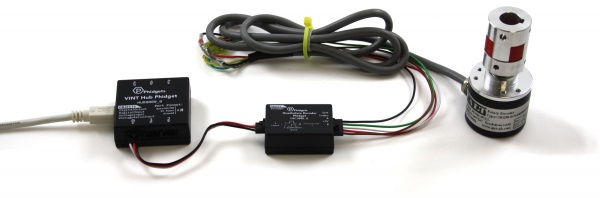
- Connect the ENC1000 to the VINT Hub using the Phidget cable.
- Connect the encoder to the Phidget using an encoder cable.
- Connect the VINT Hub to your computer using a USB cable.
Now that you have everything together, let's start using the ENC1000!
Phidget Control Panel
In order to demonstrate the functionality of the ENC1000, the Phidget Control Panel running on a Windows machine will be used.
The Phidget Control Panel is available for use on both macOS and Windows machines.
Windows
To open the Phidget Control Panel on Windows, find the ![]() icon in the taskbar. If it is not there, open up the start menu and search for Phidget Control Panel
icon in the taskbar. If it is not there, open up the start menu and search for Phidget Control Panel
macOS
To open the Phidget Control Panel on macOS, open Finder and navigate to the Phidget Control Panel in the Applications list. Double click on the ![]() icon to bring up the Phidget Control Panel.
icon to bring up the Phidget Control Panel.
For more information, take a look at the getting started guide for your operating system:
Linux users can follow the getting started with Linux guide and continue reading here for more information about the ENC1000.
First Look
After plugging the ENC1000 into your computer and opening the Phidget Control Panel, you will see something like this:
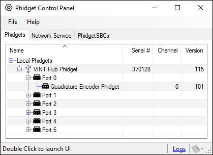
The Phidget Control Panel will list all connected Phidgets and associated objects, as well as the following information:
- Serial number: allows you to differentiate between similar Phidgets.
- Channel: allows you to differentiate between similar objects on a Phidget.
- Version number: corresponds to the firmware version your Phidget is running. If your Phidget is listed in red, your firmware is out of date. Update the firmware by double-clicking the entry.
The Phidget Control Panel can also be used to test your device. Double-clicking on an object will open an example.
Part 2: Using Your Phidget
About
Interface with any 5V quadrature encoder with the Quadrature Encoder Phidget. With an encoder, you can keep track of how far your motor has turned, which then allows you to control the position and velocity in your code.
Explore Your Phidget Channels Using The Control Panel
You can use your Control Panel to explore your Phidget's channels.
1. Open your Control Panel, and you will find the following channel:
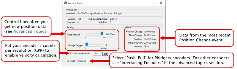
2. Double click on the channel to open the example program. This channel belongs to the Encoder channel class:
In your Control Panel, double click on "Quadrature Encoder Phidget":
Part 3: Create your Program
Part 4: Advanced Topics and Troubleshooting
Before you open a Phidget channel in your program, you can set these properties to specify which channel to open. You can find this information through the Control Panel.
1. Open the Control Panel and double-click on the red map pin icon:

2. The Addressing Information window will open. Here you will find all the information you need to address your Phidget in your program.

See the Phidget22 API for your language to determine exact syntax for each property.
The Change Trigger is the minimum change in the sensor data needed to trigger a new data event.
The Data Interval is the time (in ms) between data events sent out from your Phidget.
The Data Rate is the reciprocal of Data Interval (measured in Hz), and setting it will set the reciprocal value for Data Interval and vice-versa.
You can modify one or both of these values to achieve different data outputs. You can learn more about these properties here.
The ENC1000 can connect to any of the encoders we sell without any modification just by setting the IOMode property to Push-Pull . If you are trying to use your own encoder, you may need to change the IO mode to Open Collector or Line Driver mode. See the Encoder Primer for more details on what to use.
The encoder input on the ENC1000 uses a 5-pin, 0.100 inch pitch locking connector. The connectors are commonly available - refer to the Table below for manufacturer part numbers.
| Manufacturer | Part Number | Description |
| Molex | 50-57-9405 | 5 Position Cable Connector |
| Molex | 16-02-0102 | Wire Crimp Insert for Cable Connector |
| Molex | 70543-0004 | 5 Position Vertical PCB Connector |
| Molex | 70553-0004 | 5 Position Right-Angle PCB Connector (Gold) |
| Molex | 70553-0039 | 5 Position Right-Angle PCB Connector (Tin) |
| Molex | 15-91-2055 | 5 Position Right-Angle PCB Connector - Surface Mount |
Note: Most of the above components can be bought at Digikey.
When your program captures an encoder change event, it will receive two variables: positionChange (measured in 'ticks', four of which equal one quadrature count for the ENC1000) and timeChange (measured in milliseconds). You can use these values to easily compute the instantaneous velocity of the encoder. For example, our C# encoder example implements this method of velocity calculation:
void enc_change(object sender, Phidget22.Events.EncoderEncoderChangeEventArgs e) {

...

// Convert time change from milliseconds to minutes
double timeChangeMinutes = e.TimeChange / 60000.0;
// Calculate RPM based on the positionChange, timeChange, and encoder CPR (specified by the user)
double rpm = (((double)e.PositionChange / CPR) / timeChangeMinutes);

...

}
This implementation may be useful if you are graphing the RPM on a line graph, but if it's being used to display the current RPM as a single number, it won't be very helpful because when the motor changes speed or direction frequently, it'll be hard to read the velocity as a meaningful value. This method can also be prone to variations in velocity if the encoder's CPR is low and the sampling rate is high. To solve these problems, you should decide on a time interval during which you'll gather data, and take a moving velocity calculation based on that data. You can use the Queue data type to make this easy:
Queue<double> positionChangeQueue = new Queue<double>();
Queue<double> timeChangeQueue = new Queue<double>();

void enc_change(object sender, Phidget22.Events.EncoderEncoderChangeEventArgs e) {

double totalPosition = 0;
double totalTime = 0;
int n = 500; // sampling window size, duration is 500*t where t is the data interval of the ENC1000

// add the newest sample to the queue
positionChangeQueue.Enqueue(e.PositionChange);
timeChangeQueue.Enqueue(e.TimeChange);

// If we've exceeded our desired window size, remove the oldest element from the queue
if ( positionChangeQueue.Count >= n ) {
     positionChangeQueue.Dequeue();
     timeChangeQueue.Dequeue();
}

// Calculate totals for position and time
foreach( double positionChange in positionChangeQueue ) {

     totalPosition += positionChange;
}

foreach( double timeChange in timeChangeQueue ) {

     totalTime += timeChange;
}

// Convert time change from milliseconds to minutes
double timeChangeMinutes = e.TimeChange / 60000.0;
// Calculate RPM based on the positionChange, timeChange, and encoder CPR (specified by the user)
double rpm = (((double)e.PositionChange / CPR) / timeChangeMinutes);

}