MOT1101 User Guide: Difference between revisions
No edit summary |
No edit summary |
||
| Line 1: | Line 1: | ||
__NOINDEX__ | __NOINDEX__ | ||
__NOTOC__ | |||
<metadesc></metadesc> | <metadesc></metadesc> | ||
[[Category:UserGuide]] | [[Category:UserGuide]] | ||
== | ==Part 1: Setup== | ||
{{UGIntro|MOT1101}} | {{UGIntro|MOT1101}} | ||
* A [{{SERVER}}/products.php?product_id=MOT1101 MOT1101 Spatial Phidget] | * A [{{SERVER}}/products.php?product_id=MOT1101 MOT1101 Spatial Phidget] | ||
| Line 16: | Line 17: | ||
<br clear="all"> | <br clear="all"> | ||
==Using the MOT1101== | {{UGcontrolpanel|MOT1101}} | ||
== Part 2: Using Your Phidget == | |||
===About=== | |||
The MOT1101 combines an accelerometer (±8g), gyroscope (± 2000°/s), and magnetometer (± 8 G). Each sensor measures in the x, y, and z-axis. You can also use the Spatial object to obtain data from all three sensors, synchronized to the same timestamp. | |||
===Explore Your Phidget Channels Using The Control Panel=== | |||
You can use your Control Panel to explore your Phidget's channels. | |||
'''1.''' Open your Control Panel, and you will find the following channels: | |||
[[Image:MOT1101_Panel.jpg|link=|center]] | |||
'''2.''' Double click on a channel to open an example program. Each channel belongs to a different channel class: | |||
{{UGC-Start}} | |||
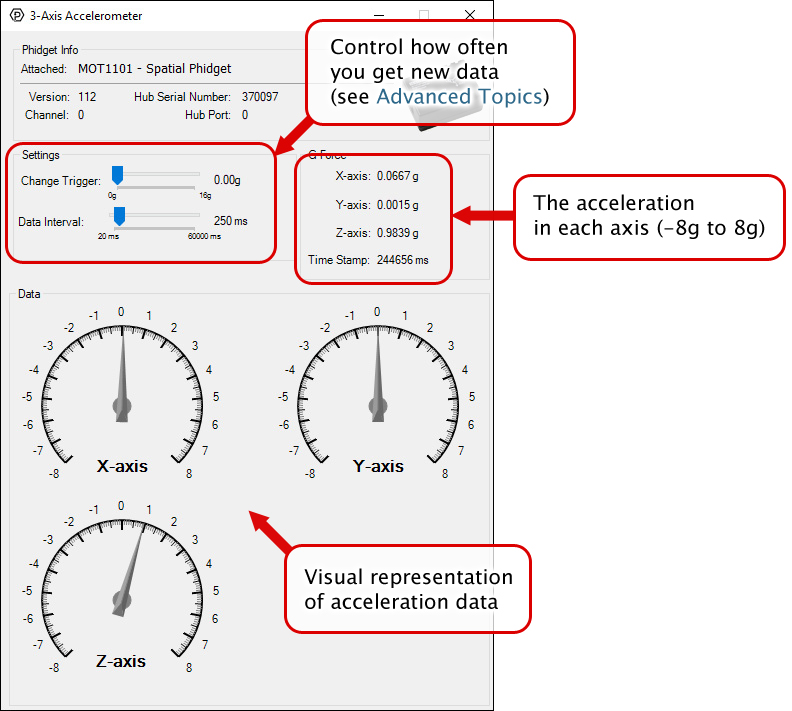
{{UGC-Entry|Accelerometer:| Reports the acceleration of the MOT1101 in the X, Y and Z axis| | |||
In your Control Panel, double click on "Accelerometer": | |||
[[Image:MOT1101-Accelerometer.jpg|center|link=]]}} | |||
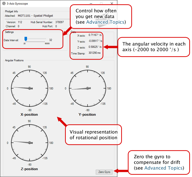
{{UGC-Entry|Gyroscope:| Reports the angular velocity of the MOT1101 along the X, Y, and Z plane| | |||
In your Control Panel, double click on "Gyroscope": | |||
[[Image:MOT1101-Gyroscope.jpg|center|link=]]}} | |||
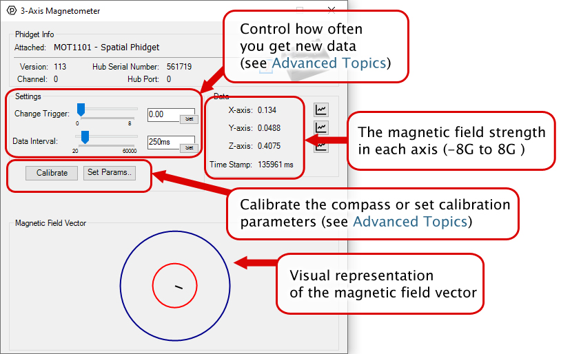
{{UGC-Entry|Magnetometer:| Reports the magnetic field strength in the X, Y, and Z-axis| | |||
In your Control Panel, double click on "Magnetometer": | |||
[[Image:MOT1101-Magnetometer.jpg|center|link=]]}} | |||
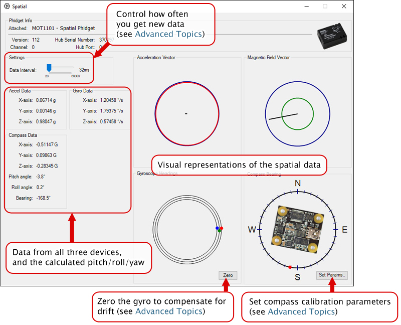
{{ | {{UGC-Entry|Spatial:| Reports synchronized data from all three objects at once (Accelerometer, Gyroscope, and Magnetometer)| | ||
In your Control Panel, double click on "Spatial": | |||
[[Image:MOT1101-Spatial.jpg|center|link=]]}} | |||
{{ | {{UGC-End}} | ||
{{ | {{UG-Part3}} | ||
{{ | == Part 4: Advanced Topics and Troubleshooting == | ||
{{UGC-Start}} | |||
{{UGC-Addressing}} | |||
{{UGC-DataInterval}} | |||
{{UGC-Entry|Compass Calibration|| | |||
In order to get numbers of useful accuracy from the MOT1101's compass you will need to provide calibration parameters. To make determining them easy, we distribute a program with our drivers that does this for you. | |||
{{ | '''To calibrate your compass:''' | ||
[[image:calibration1.png|thumb|200px|link={{SERVER}}/docs/images/3/32/Calibration1.png]] | |||
== | * Navigate to the Phidgets installation folder on your computer. Open the 'examples' folder and find the Compass Calibrator program. | ||
<div style{{=}}"clear:both;"></div> | |||
[[image:calibration2.png|thumb|200px|link={{SERVER}}/docs/images/b/b5/Calibration2.png]] | |||
* Start the program and find the link in the Settings/Status text box. Go to the website listed. ([http://www.ngdc.noaa.gov/geomag-web/#igrfwmm]) | |||
== | <div style{{=}}"clear:both;"></div> | ||
[[image:calibration3.png|thumb|200px|link={{SERVER}}/docs/images/3/3a/Calibration3.png]] | |||
The | * Select your country and city. Click 'Get Location' and then 'Compute'. A table of values will show up in an overlaid window. The value you will need is the 'Total Field' value in nT. | ||
[[ | <div style{{=}}"clear:both;"></div> | ||
[[image:calibration4.png|thumb|200px|link={{SERVER}}/docs/images/0/02/Calibration4.png]] | |||
= | * Enter the magnetic field value into the calibration program. Note that it wants the field strength in Gauss, not nT like the website gives you. 1T {{=}} 10000 Gauss so you can divide by 1x10^5 to convert to Gauss. | ||
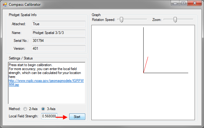
* If you are intending on mounting the MOT1101 onto a large vehicle, such as a car, you should mount the 1056 securely to the vehicle in its final intended position then check the 2-axis bubble, click the 'Start' button. | |||
* If you are using a smaller, more easily handled vehicle such as a small robot (something you could physically pick up) you will mount the MOT1101 and use the 3-axis calibration instead. Click 'Start'. | |||
<div style{{=}}"clear:both;"></div> | |||
[[image:calibration5.png|thumb|200px|link={{SERVER}}/docs/images/6/67/Calibration5.png]] | |||
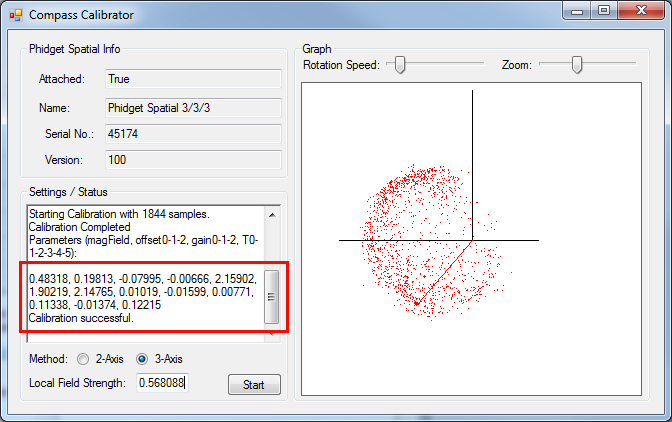
* Rotate the compass around (including attached equipment) such that the red dots being generated on screen outline a full sphere (in 3-axis). This will take several minutes. Your results may not generate an exact sphere -- but should be close to a sphere. Once done, click stop. | |||
* If you are in a large vehicle, you will be aiming to fill out a disc instead of a sphere. This can be done by simply driving around for a few minutes making sure to do complete 360° turns in the process. | |||
== | <div style{{=}}"clear:both;"></div> | ||
[[image:calibration6.png|thumb|200px|link={{SERVER}}/docs/images/8/88/Calibration6.png]] | |||
* Take the parameters displayed in the text box and use them for your compass. For example in C#: | |||
<div style{{=}}"background-color: #f3f3f3; border-color: #1c9edb; border-width:1px; border-style: dashed;"> | |||
<font size{{=}}"3"> | |||
{{ | <source lang{{=}}C#> | ||
setCompassCorrectionParameters(0.51075, 0.18820, -0.07456, -0.02209, 1.87163, 1.87640, 2.12565, -0.04000, -0.04084, -0.03552, 0.09073, -0.04258, 0.11056); | |||
</source> | |||
</font> | |||
</div> | |||
<div style{{=}}"clear:both;"></div> | |||
}} | |||
{{UGC-End}} | |||
Revision as of 21:22, 4 August 2020
Part 1: Setup
Welcome to the MOT1101 user guide! In order to get started, make sure you have the following hardware on hand:
- A MOT1101 Spatial Phidget
- VINT Hub
- Phidget cable
- USB cable and computer
Next, you will need to connect the pieces:
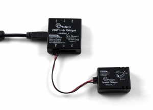
- Connect the MOT1101 to the VINT Hub using the Phidget cable.
- Connect the VINT Hub to your computer with a USB cable.
Phidget Control Panel
In order to demonstrate the functionality of the MOT1101, the Phidget Control Panel running on a Windows machine will be used.
The Phidget Control Panel is available for use on both macOS and Windows machines.
Windows
To open the Phidget Control Panel on Windows, find the ![]() icon in the taskbar. If it is not there, open up the start menu and search for Phidget Control Panel
icon in the taskbar. If it is not there, open up the start menu and search for Phidget Control Panel
macOS
To open the Phidget Control Panel on macOS, open Finder and navigate to the Phidget Control Panel in the Applications list. Double click on the ![]() icon to bring up the Phidget Control Panel.
icon to bring up the Phidget Control Panel.
For more information, take a look at the getting started guide for your operating system:
Linux users can follow the getting started with Linux guide and continue reading here for more information about the MOT1101.
First Look
After plugging the MOT1101 into your computer and opening the Phidget Control Panel, you will see something like this:
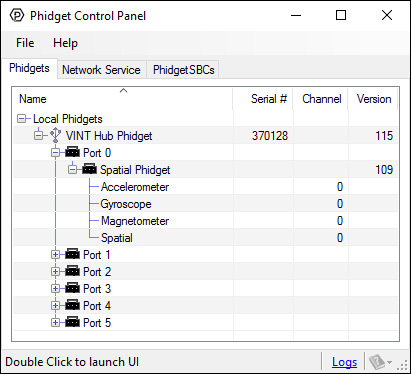
The Phidget Control Panel will list all connected Phidgets and associated objects, as well as the following information:
- Serial number: allows you to differentiate between similar Phidgets.
- Channel: allows you to differentiate between similar objects on a Phidget.
- Version number: corresponds to the firmware version your Phidget is running. If your Phidget is listed in red, your firmware is out of date. Update the firmware by double-clicking the entry.
The Phidget Control Panel can also be used to test your device. Double-clicking on an object will open an example.
Part 2: Using Your Phidget
About
The MOT1101 combines an accelerometer (±8g), gyroscope (± 2000°/s), and magnetometer (± 8 G). Each sensor measures in the x, y, and z-axis. You can also use the Spatial object to obtain data from all three sensors, synchronized to the same timestamp.
Explore Your Phidget Channels Using The Control Panel
You can use your Control Panel to explore your Phidget's channels.
1. Open your Control Panel, and you will find the following channels:
2. Double click on a channel to open an example program. Each channel belongs to a different channel class:
In your Control Panel, double click on "Accelerometer":
In your Control Panel, double click on "Gyroscope":
In your Control Panel, double click on "Magnetometer":
In your Control Panel, double click on "Spatial":
Part 3: Create your Program
Part 4: Advanced Topics and Troubleshooting
Before you open a Phidget channel in your program, you can set these properties to specify which channel to open. You can find this information through the Control Panel.
1. Open the Control Panel and double-click on the red map pin icon:

2. The Addressing Information window will open. Here you will find all the information you need to address your Phidget in your program.

See the Phidget22 API for your language to determine exact syntax for each property.
The Change Trigger is the minimum change in the sensor data needed to trigger a new data event.
The Data Interval is the time (in ms) between data events sent out from your Phidget.
The Data Rate is the reciprocal of Data Interval (measured in Hz), and setting it will set the reciprocal value for Data Interval and vice-versa.
You can modify one or both of these values to achieve different data outputs. You can learn more about these properties here.
In order to get numbers of useful accuracy from the MOT1101's compass you will need to provide calibration parameters. To make determining them easy, we distribute a program with our drivers that does this for you.
To calibrate your compass:
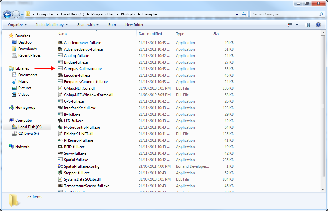
- Navigate to the Phidgets installation folder on your computer. Open the 'examples' folder and find the Compass Calibrator program.
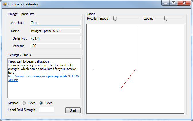
- Start the program and find the link in the Settings/Status text box. Go to the website listed. ([1])
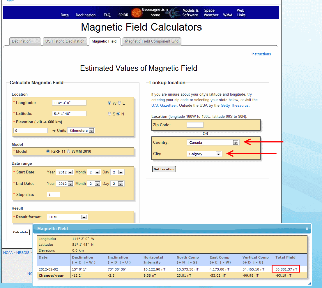
- Select your country and city. Click 'Get Location' and then 'Compute'. A table of values will show up in an overlaid window. The value you will need is the 'Total Field' value in nT.
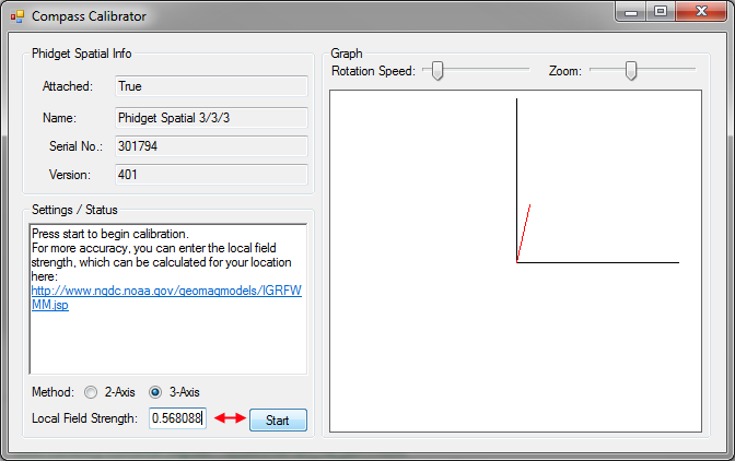
- Enter the magnetic field value into the calibration program. Note that it wants the field strength in Gauss, not nT like the website gives you. 1T = 10000 Gauss so you can divide by 1x10^5 to convert to Gauss.
- If you are intending on mounting the MOT1101 onto a large vehicle, such as a car, you should mount the 1056 securely to the vehicle in its final intended position then check the 2-axis bubble, click the 'Start' button.
- If you are using a smaller, more easily handled vehicle such as a small robot (something you could physically pick up) you will mount the MOT1101 and use the 3-axis calibration instead. Click 'Start'.
- Rotate the compass around (including attached equipment) such that the red dots being generated on screen outline a full sphere (in 3-axis). This will take several minutes. Your results may not generate an exact sphere -- but should be close to a sphere. Once done, click stop.
- If you are in a large vehicle, you will be aiming to fill out a disc instead of a sphere. This can be done by simply driving around for a few minutes making sure to do complete 360° turns in the process.
- Take the parameters displayed in the text box and use them for your compass. For example in C#:
setCompassCorrectionParameters(0.51075, 0.18820, -0.07456, -0.02209, 1.87163, 1.87640, 2.12565, -0.04000, -0.04084, -0.03552, 0.09073, -0.04258, 0.11056);