Controlling an SPI Encoder
Introduction
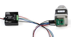
The SPI Adapter Phidget allows you to interface with a wide range of SPI-compatible devices, including sensors, displays, and more.
In this project, we will use it to control an absolute position magnetic encoder.
Steps
To complete this project, we will work through the following steps:
- Determine the device's basic configuration parameters
- Identify the sequence of commands expected by the device
- Connect the device to the SPI Adapter Phidget
- Test the device using the Phidget Control Panel
- Create a custom program.
Resources
Information from the following datasheet will be referenced throughout this project:
Demonstration
Additional Information
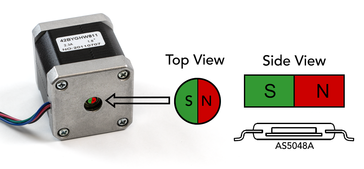
The encoder is designed to be used with a small magnet, magnetized with the poles on the edges of the cylinder instead of the top and bottom. The magnet can be attached to the exposed rear shaft of a motor, and this sensor can use the position of the magnetic field to determine the absolute position of the shaft.
Configuration Parameters
During this step, we are looking for the following information:
- Supply Voltage
- Communication Frequency
- Endianness (MSB-first or LSB-first)
- Chip Select Polarity
- SPI Wire Mode
This information is typically found using the device's product page and/or any relevant datasheets. Based on the AS5048A datasheet, we will use the following parameters:
- Supply Voltage: 3.3V or 5V (we'll use 5V)
- Communication Frequency: The clock period is 100ns minimum (10MHz maximum)
- Endianness: MSB-first
- Chip Select: Active Low
- SPI Wire Mode: Mode = 1
Command Sequence
Next, we need to determine the sequence of commands the device is expecting. Some devices have certain commands that must be sent to configure the device, but this one is ready to provide sensor data as soon as it's powered up.
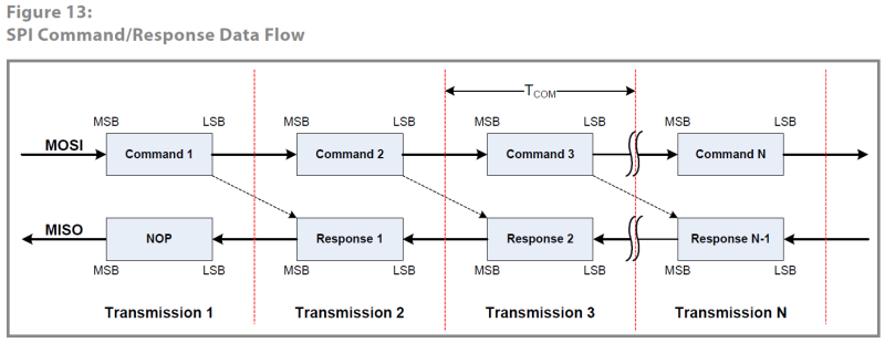
This diagram explains that each command we send will have its response delivered during the next transaction. Since our first goal is to get a stream of angle data from the encoder, we can just continuously send the Read Angle command.
Reading from AS5048A Registers
Commands sent to the encoder must follow the following format:
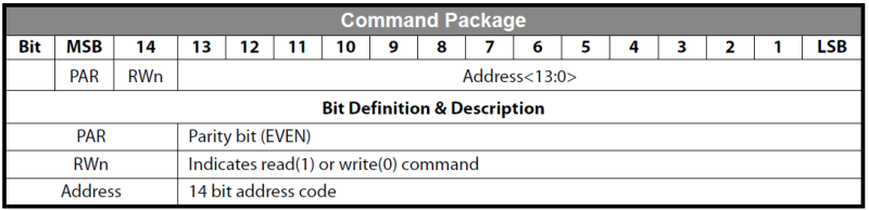
This table tells us that the 16-bit command package consists of a parity bit, a read/write bit, and then a 14-bit register address.
There are three data readout registers we can access. Here is the definition for the angle register:
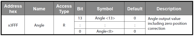
The register address for the angle data is 0x3FFF, but this is not the complete 16-bit value we need to transmit. First, we must add the R/W bit (Read=1) and then calculate the parity bit for even parity.
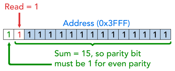
This results in 0xFFFF, which is the command we need to send with the SPI Phidget.
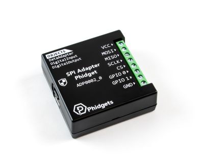
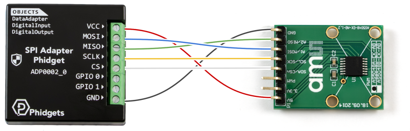
Connecting to the ADP0002
The wiring for this sensor is very straightforward with the ADP0002:
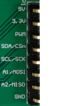
- 5V - VCC
- 3.3V - Not connected
- PWM - Not connected
- SDA/CSn - CS
- SCL/SCK - SCLK
- A1/MOSI - MOSI
- A2/MISO - MISO
- GND - GND
Testing in the Phidget Control Panel
Now that we have the configuration parameters and the command sequence, we can use the Phidget Control Panel to confirm our device is working as expected.
Reading the Angle
Reading the Angle in the Control Panel
Set the voltage to 5V, the chip select to Active Low, the wire mode to Mode_1, and the frequency to any value as they are all within the stated range.
We can try sending our 0xFFFF command we calculated in the previous step:
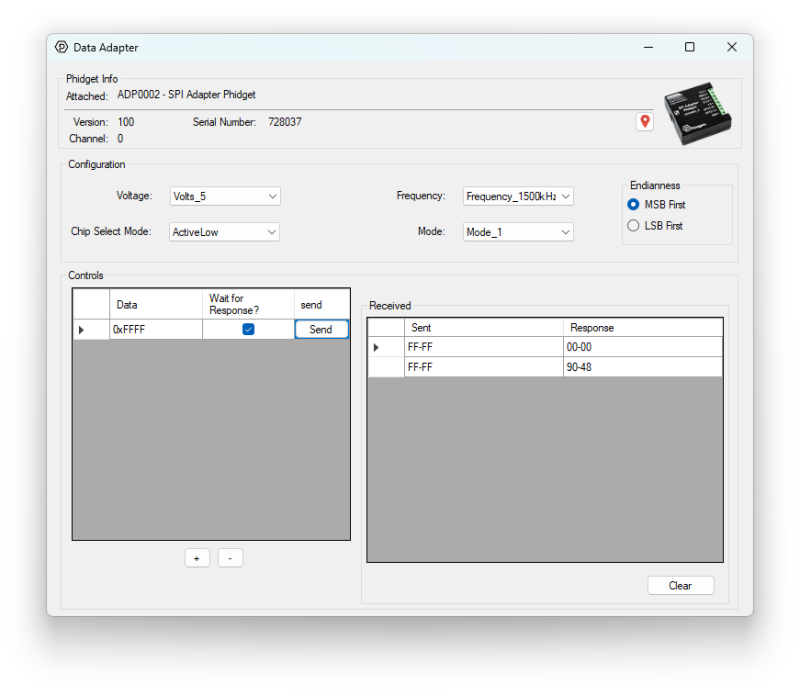
The first response is an empty 0x0000, because responses are always sent in the next transaction. After that, we start getting data back from the encoder. In order to decode these values, we must go back to the datasheet and pay attention to the read package format.
Decoding the Read Data Package
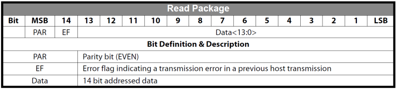
Similar to the command package, it's made up of two control bits and one 14-bit value. The control bits are a parity bit to ensure communication fidelity, and an error flag that activates if there's a problem with the previous transaction. In this example we'll ignore these bits, but in an actual deployment you'd want to be checking both of these bits on each transaction.
So to decode the response for our angle command, 0x9048, we need to strip the top two bits:
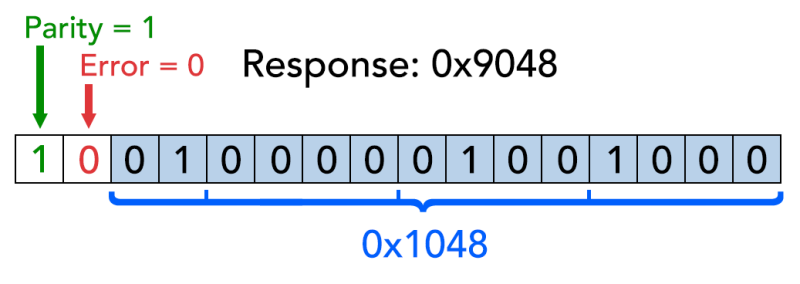
This leaves us with 0x1048, or 4168 in decimal. The encoder has 14-bit precision, so the formula is as follows:

Where 'n' is the response in decimal. Using this equation, our angle works out to 91.58 degrees. When we eventually write our own program, we'll handle all of this bit manipulation and unit conversion in code.
Zeroing the Encoder
The advantage of an absolute encoder is that the actual angle of the shaft will be known as soon as the system is powered, without need for calibration or homing. This also means that the "home position" of our rotary system will be an arbitrary angle. We could zero this by keeping track of the initial angle in our program, but this chip has its own zeroing feature, so let's take a look.
Zeroing Command Registers and Sequence
We can find the zeroing process in the datasheet:
- Clear zero position registers by writing '0' into them
- Read the current angle
- Write the angle into the zero position registers
- (optional) Burn the value into the register so it persists across power cycles
For now we'll only do the steps 2 and 3, since the zero position registers will already be zero on startup by default since we haven't burned a value into the register. In our final program we'll be using the zero as a sort of 'tare' function so we will have to do the first step there. Here are the zero register definitions:
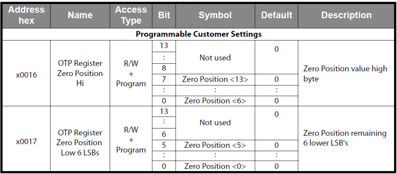
Just as before, we need to add the proper control bits to these address values before we send them.
- Write to Zero Position Hi: 0x0016 -> 0x8016
- Write to Zero Position Lo: 0x0017 -> 0x0017
For each of these registers, we'll follow this flow:
- Write to the zero position command
- Send the angle data
- Send a NOP (empty command) to confirm data sent
Zeroing in the Control Panel
In this example, our received data is 0xBB99. Stripping the control bits, we get 0x3B99 or 11 1011 1001 1001 in binary. According to the zero register definitions, we need the 6 least significant bits in the low register, and the other 8 in the high register. This gives us:
- LSB: 0b011001 (0x19) -> 0x8019
- MSB: 0b11101110 (0xEE) -> 0x00EE
Again, since we need to set the write bits and proper parity, we end up with 0x8019 and 0x00EE. Here's what the zeroing process looks like in the control panel (annotations added for clarity):
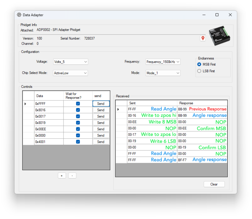
There are no error bits set in the responses, and each register we set echoed back the correct value when we wrote to it. The angle response we got after zeroing is 0xBFF7.
- Strip control bits -> 0x3FF7
- Convert to decimal -> 16375
- Angle formula -> 359.80°
Since our new angle is close to 360° (the same as 0°), it looks like the zeroing process was successful.
Writing a Custom Python Script
To begin writing a custom program for your Phidget device, navigate to the product page and select the Code Samples tab. From there, you can customize the code for your own purposes. Here we have modified the code sample to demonstrate a simple readout of the encoder angle:
from Phidget22.Phidget import *
from Phidget22.Devices.DataAdapter import *
import time

def hex2angle(hex):
	bytes = (hex[0] << 8) | hex[1]      # Combine MSB and LSB
	bytes = bytes & 0b0011111111111111  # Discard top two bits (parity and error flag bits)
	angle = round(bytes / 16348*360,3)  # Divide by 2^14, multiply by 360 to get degrees
	return angle

def main():
	# Open ADP0002
	adp = DataAdapter()
	adp.openWaitForAttachment(5000)

	# Set properties
	adp.setEndianness(DataAdapterEndianness.ENDIANNESS_MSB_FIRST)
	adp.setFrequency(DataAdapterFrequency.FREQUENCY_1500kHz)
	adp.setDataAdapterVoltage(DataAdapterVoltage.DATAADAPTER_VOLTAGE_5_0V)
	adp.setSPIChipSelect(DataAdapterSPIChipSelect.SPI_CHIP_SELECT_ACTIVE_LOW)
	adp.setSPIMode(DataAdapterSPIMode.SPI_MODE_1)
	time.sleep(0.5)

	# Read and print angle until keyboard interrupt
	print("Printing encoder data. Press CTRL+C to quit.")
	try:
		while True:
			recvData = adp.sendPacketWaitResponse([0xFF,0xFF])
			print(f"\rEncoder Angle: {hex2angle(recvData)}    ",end="",flush=True)
			time.sleep(0.1)

	except KeyboardInterrupt:
		pass

	adp.close()

main()
That’s about it, we went from reading the datasheet to a working script. Not all datasheets are created equal, so if you’re struggling with getting your sensor set up, feel free to ask for help by sending us an email.
Full Script
Here is the full Python script that was used in the demonstration video. It displays the encoder angle and also provides the option to zero the encoder.
from Phidget22.Phidget import *
from Phidget22.Devices.DataAdapter import *
import time
import threading

# Register definitions from datasheet
ANGLE = [0x3F,0xFF]
MAGNITUDE = [0x3F,0xFE]
DIAGNOSTIC = [0x3F,0xFD]
CLEAR_ERR = [0x00,0x01]
NOP = [0x00,0x00]
ZERO_POS_HI = [0x00,0x16]
ZERO_POS_LO = [0x00,0x17]
READ = 1
WRITE = 0

adp = DataAdapter()

# Listener for keypress during main loop
running = True
def keyboard_listener():
    global running
    while running:
        cmd = input().strip().lower()
        if cmd == "z":
            zero()
        elif cmd == "q":
            running = False

# Adds the required RW and parity bits
def addBits(packet,rw):
	bits = ((packet[0] << 8) | packet[1]) & 0x3FFF

	if(rw):
		bits = bits | 0b0100000000000000
	else:
		bits = bits & 0b1011111111111111

	if(bits.bit_count()%2 == 0):
		bits = bits & 0b0111111111111111
	else:
		bits = bits | 0b1000000000000000

	res = [(bits >> 8)& 0xFF,(bits & 0xFF)]
	return res


def zero():
	# Clear zero registers - this is needed to be able to zero more than once per run
	adp.sendPacket(addBits(ZERO_POS_HI,WRITE))
	adp.sendPacket(addBits([0x00,0x00],WRITE))
	adp.sendPacket(addBits(NOP,WRITE))
	adp.sendPacket(addBits(ZERO_POS_LO,WRITE))
	adp.sendPacket(addBits([0x00,0x00],WRITE))
	adp.sendPacket(addBits(NOP,WRITE))

	# Read current angle
	adp.sendPacket(addBits(ANGLE,READ))
	resp = adp.sendPacketWaitResponse(addBits(NOP,WRITE))

	# Combine angle bytes and mask out err/parity bits
	angle = ((resp[0] << 8) | resp[1]) & 0x3FFF

	# Split out angle for sending to zero registers
	zposm = (angle >> 6) & 0xFF
	zposl = angle & 0x3F

	# write ZPOSM (0x0016)
	resp = adp.sendPacketWaitResponse(addBits(ZERO_POS_HI,WRITE))
	resp = adp.sendPacketWaitResponse(addBits([0x00,zposm],WRITE))
	resp = adp.sendPacketWaitResponse(addBits(NOP,WRITE))

    # write ZPOSL (0x0017)
	resp = adp.sendPacketWaitResponse(addBits(ZERO_POS_LO,WRITE))
	resp = adp.sendPacketWaitResponse(addBits([0x00,zposl],WRITE))
	resp = adp.sendPacketWaitResponse(addBits(NOP,WRITE))

def hex2angle(hex):
	bytes = (hex[0] << 8) | hex[1]      # Combine MSB and LSB
	bytes = bytes & 0b0011111111111111  # Discard top two bits (parity and error flag bits)
	angle = round(bytes / 16348*360,3)  # Divide by 2^14, multiply by 360 to get degrees
	return angle

def main():
	# Open ADP0002
	adp.openWaitForAttachment(5000)

	# Set properties
	adp.setEndianness(DataAdapterEndianness.ENDIANNESS_MSB_FIRST)
	adp.setFrequency(DataAdapterFrequency.FREQUENCY_1500kHz)
	adp.setDataAdapterVoltage(DataAdapterVoltage.DATAADAPTER_VOLTAGE_5_0V)
	adp.setSPIChipSelect(DataAdapterSPIChipSelect.SPI_CHIP_SELECT_ACTIVE_LOW)
	adp.setSPIMode(DataAdapterSPIMode.SPI_MODE_1)
	time.sleep(0.5)

	# Start thread for keypress detection during the loop
	threading.Thread(target=keyboard_listener, daemon=True).start()
	print("Printing encoder data. Press 'z' to zero and 'q' to quit.")

	# Read and print angle until 'q' pressed
	try:
		while running:
			recvData = adp.sendPacketWaitResponse(addBits(ANGLE,READ))
			print(f"\rEncoder Angle: {hex2angle(recvData)}    ",end="",flush=True)
			time.sleep(0.1)

	except KeyboardInterrupt:
		pass

	adp.close()

main()