1135 User Guide
Getting Started
Welcome to the 1132 user guide! In order to get started, make sure you have the following hardware on hand:
- 1132 - 4-20mA Adapter
- Any Phidget with a Voltage Input port, here are some compatible products. We will be using the VINT Hub for this guide.
- USB cable and computer
- Phidget cable
- voltage source
Next, you will need to connect the pieces:
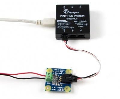
- Connect the 1135 to the HUB0000 with the Phidget cable.
- Connect a voltage source to the 1135. If you connect the supply backwards, the reported voltage will be negative.
- Connect the HUB0000 to your computer with the USB cable.
Now that you have everything together, let's start using the 1135!
Using the 1135
Phidget Control Panel
In order to demonstrate the functionality of the 1135, we will connect it to the HUB0000, and then run an example using the Phidget Control Panel on a Windows machine.
The Phidget Control Panel is available for use on both macOS and Windows machines. If you would like to follow along, first take a look at the getting started guide for your operating system:
Linux users can follow the getting started with Linux guide and continue reading here for more information about the 1135.
First Look
After plugging in the 1135 into the HUB0000, and the HUB0000 into your computer, open the Phidget Control Panel. You will see something like this:
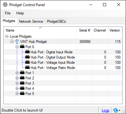
The Phidget Control Panel will list all connected Phidgets and associated objects, as well as the following information:
- Serial number: allows you to differentiate between similar Phidgets.
- Channel: allows you to differentiate between similar objects on a Phidget.
- Version number: corresponds to the firmware version your Phidget is running. If your Phidget is listed in red, your firmware is out of date. Update the firmware by double-clicking the entry.
The Phidget Control Panel can also be used to test your device. Double-clicking on an object will open an example.
Voltage Input
Double-click on a Voltage Input object in order to run the example:
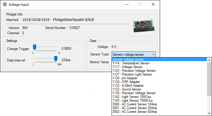
General information about the selected object will be displayed at the top of the window. You can also experiment with the following functionality:
- Modify the change trigger and/or data interval value by dragging the sliders. For more information on these settings, see the data interval/change trigger page.
- Select the 1135 from the Sensor Type drop-down menu. The example will now convert the voltage into differential voltage (V) automatically. Converting the voltage to differential voltage (V) is not specific to this example, it is handled by the Phidget libraries, with functions you have access to when you begin developing!
Technical Details
General
The 1135 measures the differential voltage between the input terminals and outputs the difference proportionally. The maximum differential voltage that can be measured accurately is ±30V. When the positive and negative inputs are equal, the voltage output value is 2.5V. When the positive input is 30V greater than the negative input, the voltage output is 4.5V and when the positive input is 30V less than the negative input, the voltage output is 0.5V.
When measuring voltage levels below 5V, you'll have more accuracy if you connect the leads directly to the voltage input of the HUB0000 (or compatible product).
Since the 1135 can measure a differential voltage, the common mode rejection (CMR) is an important specification. CMR refers to the amount of voltage that both input terminals of a differential amplifier can be offset without affecting the output gain. For example, if the positive terminal sees a voltage of 7V and the negative terminal sees a voltage of 5V, then the CMR would be 5V and would output a value of 2V at unity gain. For the 1135, it is able to measure the differential voltage of ±10V with a CMR of 40V while keeping the accuracy within 2%. Please note that the error specifications do not include the error introduced by the Analog to Digital Conversion on the Analog Input. (if you are using the 1135 with a PhidgetInterfaceKit) The majority of error introduced by the Analog to Digital conversion is from the error in the voltage reference (0.5% max), and the limitation of resolution in the analog-to-digital converter. The best accuracy can be achieved by using a 2 or more point calibration of your system - effectively calibrating the 1135 and the PhidgetInterfaceKit in a single step. If you are calibrating, be sure to use a good quality multimeter to determine the voltage being applied.
Formulas
The Phidget libraries can automatically convert sensor voltage into differential voltage (V) by selecting the appropriate SensorType. See the Phidget22 API for more details. The Formula to translate the analog voltage returned by the 1135 into differential voltage is:

where Vdiff is defined as Vpositive - Vnegative, and Vsens is the voltage returned by the 1135. For maximum accuracy, measure the sensor voltage when measuring a 0V source and replace the "2.5" in this equation with the zero value that you've measured.
Phidget Cable
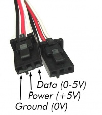
The Phidget Cable is a 3-pin, 0.100 inch pitch locking connector. Pictured here is a plug with the connections labelled. The connectors are commonly available - refer to the Analog Input Primer for manufacturer part numbers.
What to do Next
- Programming Languages - Find your preferred programming language here and learn how to write your own code with Phidgets!
- Phidget Programming Basics - Once you have set up Phidgets to work with your programming environment, we recommend you read our page on to learn the fundamentals of programming with Phidgets.