1122 User Guide
Getting Started
Welcome to the 1122 user guide! In order to get started, make sure you have the following hardware on hand:
- 1122 - 30 Amp Current Sensor AC/DC
- Any Phidget with a Voltage Ratio Input port, here are some compatible products. We will be using the VINT Hub for this guide.
- USB cable and computer
- Phidget cable
- A current-carrying wire to test the sensor
Next, you will need to connect the pieces:
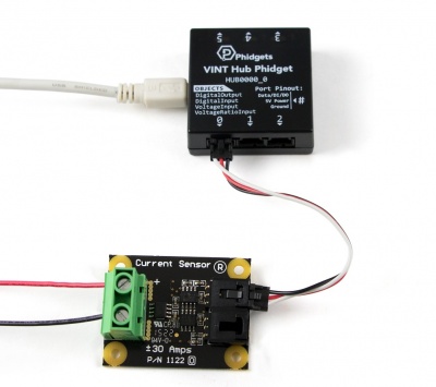
- Connect the 1122 to the HUB0000 with the Phidget cable.
- To measure alternating current, you can either use the DC port to measure a peak-to-peak AC signal, or you can use the AC port to measure the RMS value. To measure direct current, either the AC port or the DC port will work, since RMS calculations will have no effect on a DC signal.
- Connect the current-carrying wire into the terminals of the current sensor, paying attention to polarity. For safety, ensure that the wire is not powered until you're finished connecting everything.
- Connect the HUB0000 to your computer with the USB cable.
Now that you have everything together, let's start using the 1122!
Using the 1122
Phidget Control Panel
In order to demonstrate the functionality of the 1122, we will connect it to the HUB0000, and then run an example using the Phidget Control Panel on a Windows machine.
The Phidget Control Panel is available for use on both macOS and Windows machines. If you would like to follow along, first take a look at the getting started guide for your operating system:
Linux users can follow the getting started with Linux guide and continue reading here for more information about the 1122.
First Look
After plugging in the 1122 into the HUB0000, and the HUB0000 into your computer, open the Phidget Control Panel. You will see something like this:
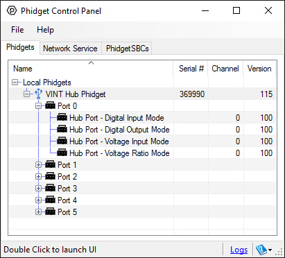
The Phidget Control Panel will list all connected Phidgets and associated objects, as well as the following information:
- Serial number: allows you to differentiate between similar Phidgets.
- Channel: allows you to differentiate between similar objects on a Phidget.
- Version number: corresponds to the firmware version your Phidget is running. If your Phidget is listed in red, your firmware is out of date. Update the firmware by double-clicking the entry.
The Phidget Control Panel can also be used to test your device. Double-clicking on an object will open an example.
Voltage Ratio Input
Double-click on a Voltage Ratio Input object in order to run the example:
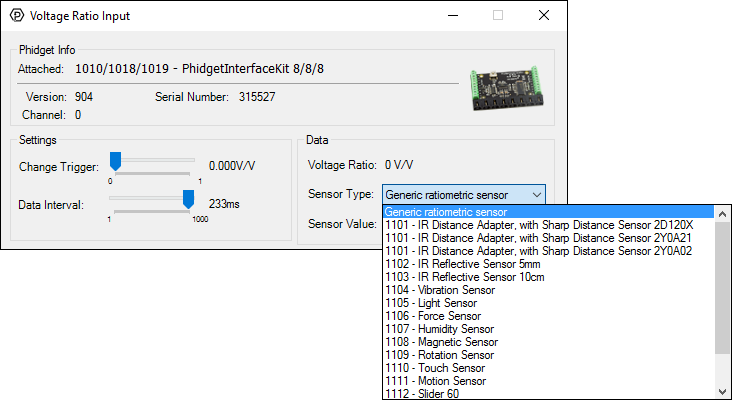
General information about the selected object will be displayed at the top of the window. You can also experiment with the following functionality:
- Modify the change trigger and/or data interval value by dragging the sliders. For more information on these settings, see the data interval/change trigger page.
- Select the 1122 from the Sensor Type drop-down menu. The example will now convert the voltage into amperage (A) automatically. Converting the voltage to amperage (A) is not specific to this example, it is handled by the Phidget libraries, with functions you have access to when you begin developing!
Technical Details
General
The 1122 measures alternating current (AC) up to 30 Amps and direct current (DC) between –30 and +30 Amps. It uses a Hall effect based sensor to measure the magnetic field induced by the applied current flowing through a copper conductor. It then converts the magnetic data into a current measurement with internal calculations. The AC output will give the root mean square (RMS) value of an alternating current assuming the current is sinusoidal, and the sine wave is varying equally across the zero point. The AC output can also be used for signals that are not varying evenly around the zero point but the value will be the RMS plus a DC component. If a DC signal is being measured, the AC output will produce a signal that can be used to calculate the current but without the value representing direction of current flow.
Measuring Current
The 1122 should be wired in series with the circuit under test, as shown in the following diagrams:
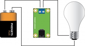
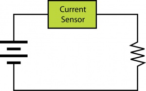
In the diagrams above, the voltage source is represented by the battery symbol. The load is represented by a light bulb or schematic resistor symbol. The current flowing from the battery to the load is measured through the current sensor.
Formulas
The Phidget libraries can automatically convert sensor voltage into amperage (A) by selecting the appropriate SensorType. See the Phidget22 API for more details. The formula to translate voltage ratio from the sensor into amperage is:


Phidget Cable
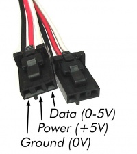
The Phidget Cable is a 3-pin, 0.100 inch pitch locking connector. Pictured here is a plug with the connections labelled. The connectors are commonly available - refer to the Analog Input Primer for manufacturer part numbers.
What to do Next
- Programming Languages - Find your preferred programming language here and learn how to write your own code with Phidgets!
- Phidget Programming Basics - Once you have set up Phidgets to work with your programming environment, we recommend you read our page on to learn the fundamentals of programming with Phidgets.