|
Notice: This page contains information for the legacy Phidget21 Library. Phidget21 is out of support. Bugfixes may be considered on a case by case basis. Phidget21 does not support VINT Phidgets, or new USB Phidgets released after 2020. We maintain a selection of legacy devices for sale that are supported in Phidget21. We recommend that new projects be developed against the Phidget22 Library.
|
Encoder Primer
|
|
Introduction
Encoders are a type of sensor that measures the movement of a mechanical part. For example, a rotary encoder can measure the rotation of a motor, or the position of a dial or knob. A linear encoder could measure the position of a piston in a robot, or it could be used in a digital caliper to precisely measure the width of the object it's gripping. Both devices work on the same principle, but a rotary encoder can be thought of as a linear encoder that has been "rolled up" into a circle. The majority of the information on this page will be about rotary encoders (particularly quadrature encoders), although much of it can be applied to linear encoders because of their similarity.
Encoders are often used in control systems, as a type of feedback to ensure that a mechanical part is moving exactly as much as planned. For example, when you normally use a DC motor, it will simply spin as fast as it can based on how much power you provide it with. If you use a motor controller, you have control over the direction of the rotation and the approximate speed of the motor, but still have no way to tell your software what exactly the motor is doing in the physical world. If you also use an encoder, you can give your program access to the motor's current position, allowing it to make fine adjustments to speed and position.
How they work
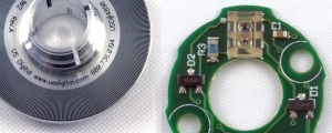
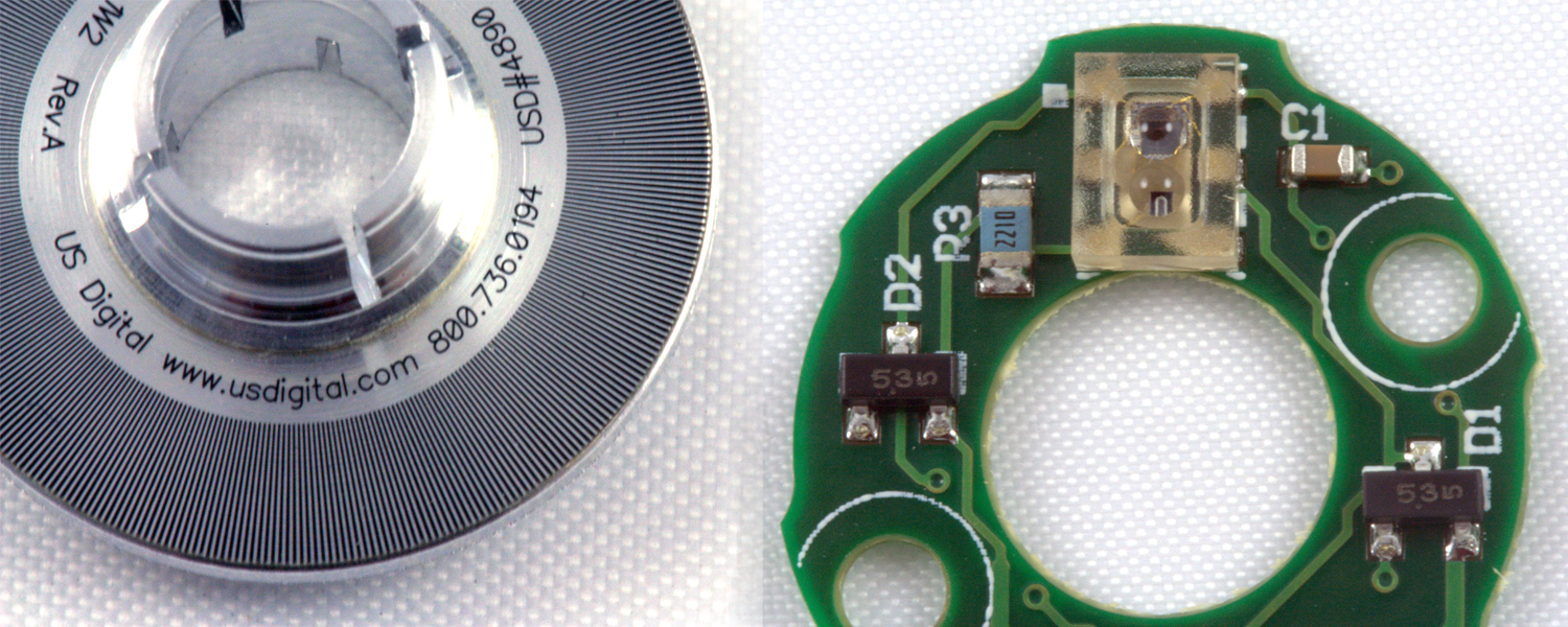
On the left is an encoder disk for a US Digital optical encoder. The thin lines around the edge of the disk are read by a pair of phototransistors, which are encased in plastic on the top of the circuit board in the right image. One phototransistor is slightly offset from the other, in order to generate a quadrature signal.
Full-sized Image
An encoder has two major components- a disk, and a detector. The disk is covered with a unique pattern that the detector will be able to read when it moves across them. For example, optical encoders use light sensors to read the contrasting sections on the surface, while a mechanical encoder uses brushes to read gaps in a metal surface on a circuit board. As the detector moves across the pattern, the encoder generates a signal. The encoder then sends this detected pattern out to be processed by the encoder interface. You can learn about the specific details of the wide variety of encoder types in the Types of Encoders section. The most common method to send out the rotational information from the encoder to the encoder interface is Quadrature Encoding.
Quadrature Encoding
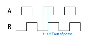
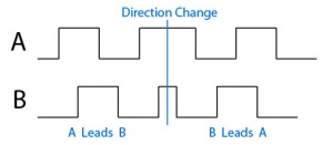
Quadrature encoding is an incremental signal method that encoders use to report a change in position and the direction of change. There are two channels, Channel A and Channel B, and they both have a high and a low voltage state (usually 0V and 5V). When the reader for channel A passes over a light area on the encoder disk, it generates a square pulse on channel A. The areas on the encoder wheel or the readers are slightly offset so the reader for channel B will detect a pattern 90° out of phase from the reader for channel A. By reading the number of pulses and which channel is ahead of the other (called "leading"), the encoder interface can tell how far the encoder has rotated, and in which direction. Some encoders also have a third channel, called an index channel, which sends a pulse once every complete rotation. This allows the encoder to know its actual position instead of its relative position, like an absolute encoder, without incurring too much additional cost. You can check your encoder's data sheet to see if it has an index channel.

In order to interpret this pulse data sent out by the quadrature encoder, you need to connect it to an encoder interface. The interface will convert the signals sent from the encoder into a number of "counts" or "cycles" which can be converted into number of rotations based on the encoder's CPR (Counts/Cycles per Rotation). The terminology surrounding this specification for encoders can be confusing because there is no consistently agreed upon term to describe these units. Some retailers may call these "pulses" or they might use any of these terms to describe each edge in the signal. In this document, and the rest of the Phidgets Inc. documentation, we will use the term "Cycle" to refer to a complete quadrature cycle, and the term "Edge" will refer to a single rising or falling edge of a pulse in the quadrature signal. It's useful to get this terminology straightened out when talking about the resolution of an encoder interface.
Interface Resolution
There are a few ways the encoder interface can interpret the quadrature data. You need to know the resolution of your interface in order to know how much physical rotation is represented by one count of the position variable. The encoder interface can update the position variable once per quadrature cycle (that is, when a full pulse has been seen on both channel A and channel B)- this would be considered to have a resolution of "1x". Or, it could update the position variable twice per quadrature cycle- once when it sees a rising edge on both channels, and again when it sees a falling edge on both channels. The resulting position variable would therefore have double the resolution, so the encoder interface's resolution would be "2x". If even more precision is required, the encoder interface could update the position variable whenever an edge is detected on either channel. This would result in a position variable that is "4x" more precise than usual. However, not every encoder interface has the ability to detect these edges precisely enough to get 4x or 2x resolution. In order to figure out how much of the position variable corresponds to a full rotation of your encoder, take the Cycles per Rotation of the encoder and multiply it by the encoder interface resolution.
Encoder Interfaces
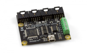
An encoder interface is a device that converts encoder data into a useful format, such as number of counts and direction of rotation. For example, the 1057_2 - PhidgetEncoder HighSpeed reads in a pair of quadrature signals, and uses them to continually update the position of the encoder, automatically taking care of direction changes. These updates are sent to your computer via USB, and when your program makes a call to get the encoder's position, it retrieves the latest value that has been sent. The speed at which these updates occur is called the Software Update Rate. The encoder interface will also typically provide operating power to the encoder. Phidgets Inc. encoder interfaces supply +5V, which is a common voltage requirement for many encoders. If you're planning on using an optical encoder with one of our encoder interfaces, you should make sure that it's rated for +5V operation. Mechanical encoders, on the other hand, usually don't require the +5V pin at all- they just use the pull-up voltage on the data lines and switch to ground to generate the signal.
Even if you're up to the task of trying to decode the quadrature signal yourself in software, we do not recommend it, because the Digital Inputs on Phidgets devices do not sample fast enough to detect a quadrature signal.
The Digital Inputs on Phidgets devices do not sample fast enough to properly detect a quadrature signal, so even if you want to try to decode the quadrature signal in software, you would need another device that can sample fast enough to accurately pick up the signal.
Connector
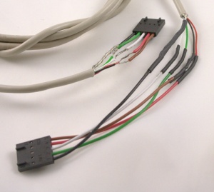
The encoders available at Phidgets, Inc. have either four or five wires in the connector:
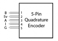
- B Channel - This is one of the output channels the encoder uses to report changes in its position.
- +5V - This wire supplies power to the encoder.
- A Channel - This is the other output channel the encoder uses to report changes in its position.
- Index (Optional) - This is an output channel that some encoders have. It sends a pulse every time the encoder makes a full rotation.
- Ground - This wire supplies a ground to the encoder.
The encoder interfaces sold at Phidgets, Inc. are compatible with both four-pin and five-pin encoders, although not all of them can use the index channel. Check the product information for your interface to find out if it supports the index channel.
The four-wire encoders still use a 5-wire connector, with the index wire not included. This means you can still use these encoders with encoder interfaces that normally accept 5-wire encoders.
Here's a list of encoder cables available at Phidgets Inc.:
(table: +cable +needs_encoder_input)
| Phidgets Product # | Connector Type | Length (cm) |
|---|---|---|
| 3019_0 | Molex 50-57-940 | 50 |
| 3032_0 | E4P | 50 |
Types of encoders
Rotary vs. Linear
A rotary encoder measures rotation and is often used in dials and knobs, or on the shaft of a motor to keep track of its position.
A linear encoder measures distance and is typically used in applications that involve precise linear movement, such as digital calipers, scanners, and various robotic applications. They are usually meant for specialized applications and are more expensive than most rotary encoders.
Absolute vs. Incremental

The diagram on the left shows a simplified example of an incremental quadrature encoder disk, with separate tracks for the A and B channels. The diagram on the right is a simplified representation of an absolute grey code encoder disk.
An incremental encoder uses a series of thin lines on the read surface to keep track of its position. The most common kind of incremental encoder is called a quadrature encoder, which uses two sets of these lines, slightly offset. This allows the encoder to detect the position relative to the starting position, even if the encoder changes direction. Incremental encoders provide output in the form of a series of pulses. This topic is explained further in the Output Circuit section.
An absolute encoder uses a pattern of concentric rings on the encoder disk to keep track of its position. Each ring provides additional accuracy- the innermost ring reveals which half of the encoder the sensors are currently on, the next one shows which quarter of the encoder the sensors are reading, and so on. Many absolute encoders also have an extra inner track that is the same size as the first, which allows the use of grey code instead of ordinary binary. The advantage to an absolute encoder is that you can immediately tell the position of the encoder as soon as it turns on, since each position on the encoder disk corresponds to a unique sequence of binary bits. The downside of an absolute encoder is that they are much more expensive than incremental encoders. Absolute encoders are not compatible with Phidgets Inc. encoder interfaces.
Read Method
Mechanical encoders consist of a series of wire brushes which move over a circuit board with a quadrature pattern. When the brushes are over a blank portion of the PCB the circuit remains open, but when the brushes contact metal on the circuit board, they close the circuit. Because of their physical complexity, mechanical encoders need to be larger than the alternatives to get the same degree of accuracy. They are rarely used for high-speed applications because the faster they move, the more likely it is that the encoder signal will be lost in noises caused by the brushes. Also, the brushes wear down quickly in high-speed applications.
Optical encoders work with the same idea as mechanical encoders except the encoder disk has a visual pattern instead of a conductive pattern. An LED in conjunction with a set of phototransistors achieve the same goal as the wire brushes in a mechanical encoder. Eliminating the need for physical contact allows them to spin much faster than a mechanical encoder. An optical encoder's maximum speed is limited by the response rate of its electronics. Optical encoders use the power supplied by the encoder interface to power their LEDs, and usually they have resistors built-in to keep the current at an optimal level. If you're using an optical encoder not sold by Phidgets Inc., you should check the data sheet to ensure that the current is limited internally. If it isn't, you might have to put a resistor in series with the +5V supply line.
Magnetic encoders have a series of magnets on the encoder disk and use Hall Effect sensors to measure the position.
Capacitive encoders work by sensing the capacitance between reader and disk. They are inexpensive and can be made thinner than other types of encoders. The main downside is that they are vulnerable to foreign materials such as dust or dirt.
Output Circuit
Absolute Encoders
Absolute encoders report their position in the form of a series of binary bits (one bit for every ring on the encoder). Some encoders convert this binary data to BCD, or gray code before sending it out.
Quadrature Encoders
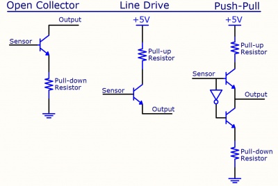
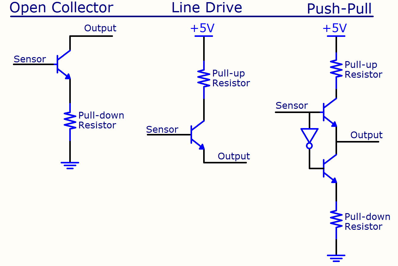
This diagram illustrates the various types of output a quadrature encoder could provide. Each quadrature channel (A, B, and sometimes Index) would have one of these circuits attached to its sensor.
Full-sized Image
Quadrature encoders have varying methods of output, which affect the resulting waveforms. These methods of output can be classified as either a Single-Ended Signal or a Differential Signal.
Single-Ended Signal
In the case of mechanical encoders, the brushes simply switch to ground without any complex circuitry. The most basic optical encoders will similarly use phototransistors to switch to ground. This method is called "Open Collector". These devices require pull-up resistors in order to generate the output waveform. They may be included in the encoder, or they may rely on the encoder interface to provide them. Phidget Inc.'s encoder interfaces come with fairly weak pull-up resistors built in. If your encoder's data sheet specifies that it requires an external pull-up resistance greater than what the Phidgets Inc. interface provides, you won't be able to use the encoder with a Phidgets Inc. interface. If your encoder needs a lower pull-up resistance (and therefore, a stronger pull-up resistor in parallel), it may still work, but at a lower response rate. If you want to make the pull-up resistor stronger, you can add pull-up resistors on the A, and B channels (and the index channel, if applicable) on the encoder cable. When choosing the resistance R for the pull-up, use the formula below (Existing resistance can be found in the data sheet of the encoder interface, and desired resistance is the pull-up resistance specified in the encoder's data sheet).


A "Line Drive" output circuit is the opposite of an open collector output- each phototransistor is connected to a pull-up resistor, so they need pull-down resistors or a sinking input to generate the output waveform. Phidgets Inc. encoder interfaces will not work with line drive encoders, because the interface does not come with built in pull-down resistors.
Another output circuit design called "Push-pull" combines the two methods above, connecting each phototransistor to both a pull-up and a pull-down resistor. A push-pull encoder will still work with a Phidgets Inc. encoder interface; the built-in pull-up resistors are unnecessary but won't cause any problems. Push-pull encoders are desirable because the output waveform can quickly transition from 0 to 5V. A shorter transition time allows the encoder to track faster movement. Another advantage of push-pull is that the output signal is less susceptible to electromagnetic interference, because the output is always supplied directly by either +5V or ground.
Differential Signal
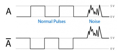
This diagram illustrates how a differential encoder is able to ignore noise. Channel Ā is the inverse of channel A, generated inside the encoder. However, when noise is introduced along the wire between the encoder and the encoder interface, the noise will be almost identical on both channels. Since the noise is not inverted on channel Ā, the differential encoder interface can perform a few simple operations to filter out the noise.
Differential encoders greatly reduce susceptibility to noise by starting with a push-pull quadrature encoder and then adding an additional push-pull driver for each signal line (A, B and I). In each driver pair, one driver is always transmitting the opposite of the other. This redundancy allows each signal to be interpreted relative to its inverse, rather than relative to ground. Since two wires in the same environment will experience very similar interference, the differential encoder interface will be able to tell the difference between a real pulse and noise. Another advantage of a differential encoder is that it emits less electromagnetic interference.
Phidgets Inc.'s encoder interfaces do not support differential encoders, although as long as the quadrature signal is still in the form of 0-5V pulses, you could just hook up the non-inverted wire from each pair (which would cause it to act like a normal single-ended quadrature encoder with no protection against interference).
Choosing an encoder
The first thing to consider when choosing an encoder is what degree of accuracy you are going to require. Is the application a simple human interface (knob or something similar) or are you trying to precisely track the movement of a motor? Mechanical encoders have the advantage of being extremely cheap, but they don't have as high accuracy as optical encoders. For applications that don't require accuracy, they are sufficient. For any situation where you need high accuracy, the best choice is an optical encoder.
Rotary encoders often advertise having a "detent". This means that the encoder will have perceptible clicks as it rotates and snaps into position. These types of encoders are best for applications where the encoder will be turned by people, such as a knob or dial. Some of these encoders will also include a pushbutton switch on the shaft, so that a dial can have a secondary function when it is pushed. Many of our encoder interfaces have digital inputs included so that these switches can be wired into the same board as the encoder. This feature can be useful if you want one encoder to perform two functions- for example, it could control the volume of a speaker when it's rotated with the dial not pushed in, and it could effect the stereo balance when it's rotated with the dial pushed in.
If you want to buy an encoder to use with Phidgets Inc. encoder interfaces, you should look for encoders with quadrature output, since this is the type of signal our interfaces are meant to interpret. You should also make sure that the output signal is 0-5 volts and ensure the output circuit is compatible as described in the Output Circuit section.
Interference
One of the main concerns for encoders is their vulnerability to interference. The encoder reports how far it has moved or rotated by generating a series of pulses. If interference causes an extra pulse to be detected by the encoder interface, it gradually loses track of the encoder's true position. This is especially true when the cable between the encoder and interface is very long. If your encoder is detecting extra counts, or missing counts, there may be electromagnetic interference in your environment. A good way to test for interference is to keep the encoder stationary and monitor it to see if it registers any counts. If you have an open collector encoder, it will be more susceptible to noise when the A and B lines are at +5V, as opposed to ground. You could carefully rotate the encoder until the A and B lines read +5 volts, keep the encoder stationary and monitor it to see if it registers any counts.
The heavyweight solution to interference is using a Differential encoder and a differential interface. For a cheaper and more practical solution, you can use a single-ended encoder and connect it to the encoder interface with a section of shielded cable. Shielded encoder cables can easily be made from USB cables. Make sure you solder the ground pin to the shielding. It doesn't matter which wires the other pins are soldered to as long as you stay consistent on both ends. You can use electrical tape or heat-shrink tubing to make sure the wires don't short.
Conclusion
Encoders are sensors designed to keep track of the movement of a mechanical part, usually for the purposes of feedback control or user input.
Quadrature encoders are the most common and inexpensive solution for tracking the amount of movement and direction of movement relative to the starting position. They output position data in the form of pulses on two separate lines, which is what allows the encoder interface to determine the rotation direction.
An encoder can connect to an encoder interface, which converts the raw data from the encoder into a useful position variable, sent to your computer via USB.
There is a wide variety of encoders available, each suited to a particular application. Rotary encoders measure angular movement, like the rotation of a motor shaft, while linear encoders measure movement along a straight line, like a volume slider. Incremental encoders are able to detect movement and direction of movement relative to the encoder's starting position when it's powered up, whereas absolute encoders will always report their exact position in the form of a binary sequence. Encoders also differ in the method they use to read the encoder disk. Optical encoders use light, which passes through or bounces off contrasting sections of the encoder disk. Mechanical encoders use brushes that either float at the line voltage when at a gap in the conductive pattern on the disk, or ground out when brushing against the disk. Magnetic encoders use magnetic sensors positioned over a disk with magnetized sections, and capacitive encoders sense the change in capacitance as different parts of the disk pass between the sensor and the emitter.
Encoders can be susceptible to interference, especially when there is a long wire between the encoder and the encoder interface. This problem can be mitigated by adding shielded cable or using a differential encoder instead.
Products that fall under this category
- 1047 - PhidgetEncoder HighSpeed 4-Input
- 1057 - PhidgetEncoder HighSpeed
- 1052 - PhidgetEncoder
- 3530 - Optical Rotary Encoder ISC3004
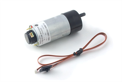
- 3254E - 12V/0.2Kg-cm/230RPM 10:1 DC Gear Motor w/ Encoder
...
Glossary
Connector
- Specify our standard encoder connector
- Steal from the 1047/1057 product manual
- Spec the connectors part numbers involved
- List of cables for encoders
Response Frequency
- If we are considering an encoder, this is one of the specs that dictates the maximum speed the encoder can turn at.
- This is the internal limitation of the electronics in the encoder. For a given encoder, this limits the maximum number of pulses/counts it can interpret per second.
- This spec should probably be destroyed, and replaced with a upper limit on how fast the encoder can turn (in RPM)
- Each encoder will have a limit dictated by the lower of the maximum mechanical rotation rate, or the response rate of the electronics.
- Is the ICS3004 360 PPR spec based on counts or pulses?
- The maximum response of a mechanical encoder depends on the amount of contact bounce. Once the encoder is turning fast enough, individual switch closures are lost in the noise.
Supply Voltage
- We should consider specifying for the encoder interfaces that they provide +5V to the encoder.
- Any encoder that connects to Phidgets should be rated for +5V operation.
- This spec is not important for mechanical encoders, that are just a series of switches. In fact, a mechanical encoder doesn't even use the +5V power supply.
- Optical encoders use the power supply for (among other things) powering LEDs. Usually optical encoders will have a series resistor on the LED to limit the current to an optimal value. If you are using an optical encoder not sold by Phidgets, please check the datasheet to ensure the LED current is limited internally - otherwise, you might have to put a series resistor on the +5V line.
Number of Pulses
- Consider renaming, or standardizing
- Counts is the lower resolution spec
- Pulses is the higher resolution spec.
- Do a survey, and figure out what is most prominent.
- We'd also have to standardize in our code samples and API documentation.
- 1065_0 returns the lower resolution value.
- Consider giving both as specs, so customers who have the wrong model (by our standard) can see the difference and infer what we mean.
Output Circuit
- In the case of a mechanical encoder, the output circuit is just switches to ground.
- In the case of optical encoders, there are a lot of different options.
- Very simple optical encoders will use phototransistors as a 'switch' to ground.
- Also called open collector.
- These encoders may have pullup resistors built into the encoder, or they may rely on the interface to provide them.
- Phidgets encoder interfaces have reasonably weak pullup resistors built into them.
- If your encoder specifies an external pullup of greater resistance than the Phidget has integrated, you won't be able to use the encoder with Phidgets.
- If your encoder needs a lower resistance (a stronger pullup), it may still work, but at a lower response rate. If you want to make the pullup stronger, you can add pullup resistors on the cable. (Show picture / diagram of this)
- Open collector is an example of a single ended drive - as opposed to differential.
- Push Pull optical encoders have more complex electronics, and they can actively drive the A/B lines high or low. The Phidget still has pullup resistors - which are not necessary, but in practice they don't cause any problems.
- Another way of saying this is that Push Pull optical encoders can respond much more quickly than the photo transistor based optical encoders - because they are not relying on pullup resistors, which have to be weak by definition. The push pull electronics can very quickly drive the cable to 0 or 1.
- Push pull is an example of a single ended drive - as opposed to differential.
- Differential output optical encoders
- Differential outputs use two push-pull drivers per signal line (A, B, I). In each driver pair, one driver is always transmitting the opposite of the other. The benefit of differential is it will emit less electromagnetic interference, and is less susceptible to electromagnetic interference on the cable introducing extra counts.
- Phidgets do not support differential optical encoders. US Digital makes an adapter board (find part number), which will convert differential signals to single ended, so differential encoders can be used with Phidgets.
- Making your encoder more immune to electromagnetic interference.
- If you are finding that your encoder is showing extra counts, or losing counts during operation, there may be electromagnetic interference in your environment, coupling into the cable.
- A good test is to leave the encoder not moving. If your encoder is open collector, it will be more susceptible to interference when the A/B lines are at +5V (as opposed to ground). If any counts appear as the encoder is still, interference is likely to blame.
- The heavyweight solution is to use a differential encoder.
- A more practical solution is to make a shielded cable.
- USB cables are easily repurposed as shielded cables.
- Show picture of USB Cable chopped up, soldered onto encoder jacks.
MAX RPM
- Merge this with the maximum RPM based on electrical limitations,
- We could indicate whether this is a mechanical or electrical limitation.
Maximum Count Rate
- For encoder interfaces
- This is the maximum count/pulse rate that the interface can receive without losing pulses.
- Have to standardize if we are talking about high or low res spec.
Internal Output Pullup Resistance
- Discussed above
- Customer can put resistors on cable in parallel if they want to lower resistance. - Put resistors on A/B channels, to +5V.
Software Update Rate (typical)
- This is how often the number of counts / pulses that have been recognized is streamed up to the PC.
- Customers often think that when they call a function, we poll the device, but actually the data is being streamed at a constant rate, and they are retrieving the latest values received by our libraries.
Encoder Input Low Voltage
- The encoder must output (on A/B/I) a voltage below this specified value to be absolutely sure the interface will interpret the signal as a 'Zero'.
- If you are unsure, you can use a multimeter to measure the voltage on A/B/I. This does not guarantee that this voltage spec will be achieved as the encoder is being operated at high speed. If you are unsure, and you have an oscilloscope, you can monitor the voltage on A/B/I during operation. Alternatively, you can operate the encoder at greater speed than you will see in your application and verify it does not lose counts.
Encoder Input High Voltage
- The encoder must output (on A/B/I) a voltage above this specified value to be absolutely sure the interface will interpret the signal as a 'One'.
- See comments above.
List of encoders
- Sourced from Digikey
- Customers should look for encoders that advertise 'Quadrature'
- Encoders often advertise 'detents' - which are perceptible clicks as the encoder is rotated. Encoders with detents are usually meant for operation by people as control knobs.
- Encoders for manual (people) operation will often have a built in pushbutton switch on the shaft. This functionality is seperate from the encoder. Encoder interfaces available from Phidgets will often have support for digital inputs - this switch can be wired in to a digital input.
Mechanical encoders
- Mechnical encoders are usually very cheap, and meant for manual (people) operation.
- Mechanical encoders will have a shorter lifespan, measured in the number of rotations.