|
Notice: This page contains information for the legacy Phidget21 Library. Phidget21 is out of support. Bugfixes may be considered on a case by case basis. Phidget21 does not support VINT Phidgets, or new USB Phidgets released after 2020. We maintain a selection of legacy devices for sale that are supported in Phidget21. We recommend that new projects be developed against the Phidget22 Library.
|
Addressing Electromagnetic Interference with Phidgets
- Phidgets are sensitive to electromagnetic interference (EMI) due to their extreme flexibility.
- Phidgets are used every day to build reliable systems, but it’s very easy to build an unreliable system.
- Very few of us have sufficient experience to effectively debug and solve EMI related problems.
Common Indication of EMI Problems
- Phidgets and other USB devices disconnect/reconnect. In your application, this will show up as detach/attach events.
- USB devices have to be unplugged/replugged to start functioning again.
- USB devices have to be plugged into a different USB port to continue functioning.
- In extreme cases, the computer has to be restarted, as the USB bus is non-functional.
- Operating systems are very conservative with their handling of USB devices. If a problem is suspected, the device will reset.
- Analog Inputs and digital inputs show up particularily noisy.
Recommended Approach to EMI Problems
We recommend following all of these guidelines. Just because your system appears to be stable, doesn’t mean it is not vulnerable. These guidelines and some possible solutions are discussed more in depth later on.
- Review grounding issues. Multiple grounds and ground loops are trouble. If your problems seem related to a sudden urge of power to your USB system, grounding may be at fault.
- Reduce emissions. Any sources of sparks or surges of current / voltage are suspect.
- Reduce vulnerability. Sensitive circuitry should be kept short. USB cables, sensor cables and digital inputs are all antennas that receive emissions.
- Add another layer of protection after the system is stable. When your system is stable under your worst-case conditions, add ferrite beads to the USB cables, and possibly to the long sensor cables and digital inputs where they connect to the Phidgets.
Grounding Problems
USB is not reliable if the voltage difference between either end of a USB cable is greater than 125mV. This is usually not a problem because the only current travelling on the USB cable should be less than 500mA (USB Maximum), and the cable resistance is designed to produce less than 125mV at 500mA current.
It’s possible to for the USB Cable to be carrying more than 500mA ground current if current is finding an alternative path back to it’s source. This can happen easily if you are using nonisolated power supplies, or using a single power supply to power multiple Phidgets.
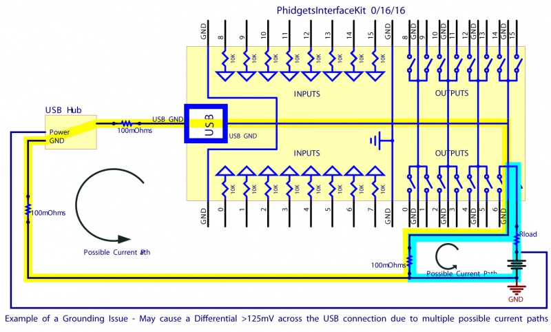
Grounding issues will manifest themselves as stability problems when using anything that consumes a lot of power, such as motors. The easiest solution is to use different power supplies for each Phidget in the system. This ensures that the current used by a Phidget (for example, the 1061 PhidgetAdvancedServo) and what it’s powering is kept within it’s domain – it recirculates between the power supply, the Phidget, and what is being powered. No extra current flows on the USB cable.
This may not be practical in some systems. Most problems can be mitigated by understanding where the current may flow, and ‘encouraging’ the current to take a particular path. We should point out that this solution may stabilize your system, but there are still current loops in the system, and these are very likely going to cause problems if you want to attain Emissions certificiations (FCC, CE, etc.)
Some Phidgets are guaranteed not to have this problem. The 1064 PhidgetMotorControl HC isolates the motors and the power supply from the USB bus. It’s impossible for the huge currents driving the motors to find their way to the USB cable.
Far Field Emissions
Far Field emissions are a form of light that cannot be seen by the human eye. They are the basis for most wireless technologies. Far Field has the ability to carry a long distance – if you suspect the disturbing influence is 50cm or more from the Phidgets, then Far Field is probably the culprit.
Some examples of Far Field emission sources
|
|

Relays switching solenoids, motors with high current loads
The noise can be reduces by suppressing the spark:
|

|
|

|
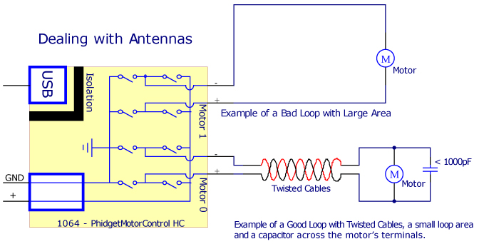
Antennas
- Loops of wire with large area
- Reduce the area by twisting the wires together that lead to the load.
Near Field Emissions
Near Field emissions are magnetic or electrical fields. In order for these to cause trouble, they have to be rapidly changing.
- Magnetic fields are caused by current. In order to reduce the strength of the magnetic field, wires carrying current (particularly varying current) should be very close to the wire carrying the return current, if not twisted around each other.
- Wiring between a motor and the motor controller is of particular concern.
- Electrical fields (Change in Voltage) cause trouble by capacitive coupling – a wire, usually an input, is affected by ‘noisy’ wires in close proximity. This will show up in a wiring harness when a weak signal, such as an input, is triggered by another wire in the harness due to a change in voltage.
- New features in Phidgets are addressing the vulnerability of input signals, by adding filtering on the digital inputs.
- Even a couple of centimeters of separation between the conflicting wires can dramatically reduce this problem.
- This is not an easy problem to solve – if in doubt, please contact Phidgets Inc.
Ferrite Beads
Ferrite beads are miracle devices for reducing high frequency problems. If clamped on a cable they will block most forms of unwanted energy. It is best to secure the ferrite bead near the end of the cable, as opposed to in the middle, to ensure the least amount of noise is affecting the cable at that end. We recommend installing a ferrite bead on USB cables close to the PC. Adding ferrite beads to long input wires close to where they attach to Phidgets will also be beneficial.
Our experimentation indicates that an extra loop through the ferrite bead is very helpful. Additional loops will often degrade protection. We suggest the ferrite bead shown above, as it is large enough to accommodate an extra loop of a USB cable, and can be easily snapped on or taken off. Digikey Part Number: 28A2736-0A2
Testing
At Phidgets, we use a 25,000 Volt spark generator to simulate problems. In the absence of such a device, a cheap electrical drill under heavy load, or pulsed near the circuit, can generate an incredible amount of EMI.
Increasing Reliability in Software
Even in very well designed systems, exceptional events can occur. The most common event is a simple detach/attach of a Phidget. This can be simulated by unplugging the Phidget when your application is operating. It is non-trivial to write an application that can handle the loss of some functionality. It’s usually necessary to start with a clear idea of the various states that can occur, what exceptions will be thrown, and how Phidgets will be re-initialized when they are available again.
Shielding
Shielding is very difficult to do well due to EMI penetrating through even the smallest holes or gaps in the shield. It is conceptually similar to sound-proofing. It would be very difficult to soundproof a system if you were not able to hear. Very few of us have the tools to measure EMI, making it difficult to be sure that our shields are helping the situation.