|
Notice: This page contains information for the legacy Phidget21 Library. Phidget21 is out of support. Bugfixes may be considered on a case by case basis. Phidget21 does not support VINT Phidgets, or new USB Phidgets released after 2020. We maintain a selection of legacy devices for sale that are supported in Phidget21. We recommend that new projects be developed against the Phidget22 Library.
|
1014 User Guide
Getting Started
Checking the Contents
|
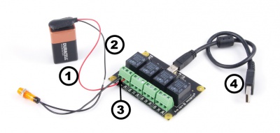
You should have received:
|
In order to test your new Phidget you will also need:
| |
Connecting the Pieces
|
| |
Testing Using Windows 2000 / XP / Vista / 7
Make sure you have the current version of the Phidget library installed on your PC. If you don't, follow these steps:
- Go to the Quick Downloads section on the Windows page
- Download and run the Phidget21 Installer (32-bit, or 64-bit, depending on your system)
- You should see the
 icon on the right hand corner of the Task Bar.
Running Phidgets Sample Program
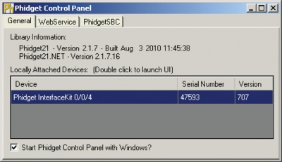
Double clicking on the ![]() icon loads the Phidget Control Panel; we will use this program to ensure that your new Phidget works properly.
icon loads the Phidget Control Panel; we will use this program to ensure that your new Phidget works properly.
The source code for the InterfaceKit-full sample program can be found in the quick downloads section on the C# Language Page. If you'd like to see examples in other languages, you can visit our Languages page.
Updating Device Firmware
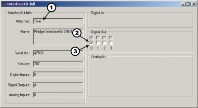
If an entry in this list is red, it means the firmware for that device is out of date. Double click on the entry to be given the option of updating the firmware. If you choose not to update the firmware, you can still run the example for that device after refusing.
|
Double Click on the |
| |
|
|
Testing Using Mac OS X
- Go to the Quick Downloads section on the Mac OS X page
- Download and run the Phidget OS X Installer
- Click on System Preferences >> Phidgets (under Other) to activate the Preference Pane
- Make sure that the Phidget InterfaceKit 0/0/4 is properly attached.
- Double Click on Phidget InterfaceKit 0/0/4 in the Phidget Preference Pane to bring up the InterfaceKit-full Sample program. This program will function in a similar way as the Windows version.
Using Linux
For a step-by-step guide on getting Phidgets running on Linux, check the Linux page.
Using Windows Mobile / CE 5.0 / CE 6.0
For a step-by-step guide on getting Phidgets running on Windows CE, check the Windows CE page.
Technical Details
Relays
A relay is an electrically-controlled switch. Although many types of electrical switches exist, a relay’s mechanical nature gives it the advantage of reliability and current-switching capacity. The main disadvantage to using mechanical relays is their limited life-span, as opposed to solid state relays who do not suffer from this drawback. For more information, check the Mechanical Relay Primer and the Solid State Relay Primer.
Using a Digital Output Relay
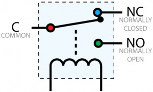
Relays have a connection scheme determined by the arrangement of contacts within the relay. Because relays are a type of switch, they are defined in the same way other electromechanical switches are defined.
In switch schemes, the number of poles represents the number of common terminals a switch has, and the number of throws represents the number of switchable terminals that exist for each pole. The relays used in the InterfaceKit 0/0/4 are SPDT relays: single pole, double throw. The internal construction of this type of relay is depicted in the diagram above. Many other types of relays exist: SPST, DPDT, and DPST, to name a few.
In an SPDT relay, one of the throw terminals is labelled Normally Closed (NC), and the other is labelled Normally Open (NO). As the name indicates, the normally closed terminal is the terminal connected to common when the relay coil is not powered. When the relay coil is energized by the relay control circuit, the electromagnetic field of the coil forces the switch element inside the relay to break its contact with the normally closed terminal and make contact with the normally open terminal. The switch element would then connect the normally open terminal and the common terminal.
Using Relays as an H-Bridge for Motor Forward/Reverse
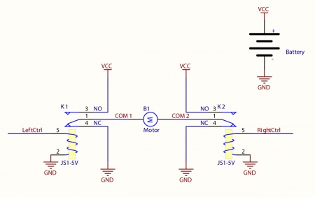
Connect the load (typically a DC Motor) to the COM terminals of the relay. The NormallyOpen (NO) terminals are connected to the power supply (VCC), and the Normally-Closed (NC) terminals are connected to the ground (GND) of the power supply. You can toggle the corresponding output to switch the relays.
Looking at the diagram, when LeftCtrl is enabled and RightCtrl is disabled, the current will flow from the NO terminal of relay K1 through the motor and into the NC terminal of relay K2. This will cause the motor to rotate in one direction.
Similarily, if LeftCtrl is disabled and RightCtrl is enabled, the current will flow from the NO terminal of relay K2 through the motor and into the NC terminal of relay K1. This will cause the motor to rotate in the opposite direction.
When both LeftCtrl and RightCtrl are disabled, both ends of the motor will be shorted to ground and no current will flow. When both leftCtrl and RightCtrl are enabled, both ends of the motor will be shorted to VCC and again, no current will flow.
Wetting Current
When a relay is in one switch position for a period of time, oxidation of the open contact(s) can occur. Depending upon the internal coating material of the contacts, oxide films of varying density will be displaced upon the surface of open contacts; this film acts as an insulator to current flow. When the relay is switched, a certain amount of current flowing through the contacts, known as the wetting current, is required to remove the film of oxides and ensure proper conduction. Because of this requirement, these relays are not reliable for signal switching. Check the specification table for your relay board to find out the Minimum Load Current ("Wetting Current").
Load Noise
If highly inductive loads are used with the InterfaceKit, it is recommended that a noise limiting component be used to prevent damage to the device. An MOV, TVS diode, or kickback diode (for DC applications) shunted across the load will assist in dissipating voltage transients.
API
We document API Calls specific to this product in this section. Functions common to all Phidgets and functions not applicable to this device are not covered here. This section is deliberately generic. For calling conventions under a specific language, refer to the associated API manual in the Quick Downloads section for that language. For exact values, refer to the device specifications.
Functions
int OutputCount() [get] : Constant = 4
- Returns the number of digital outputs supported by this PhidgetInterfaceKit.
bool OutputState (int OutputIndex) [get,set]
- Sets/returns the state of a digital output. Setting this to true will activate the output, False is the default state. Reading the OutputState immediately after setting it will not return the value set - it will return the last state reported by the Phidget.
Events
OnOutputChange(int OutputIndex, bool State), [event]
- An event that is issued when the state of a digital output changes.
Product History
| Date | Board Revision | Device Version | Comment |
|---|---|---|---|
| August 2002 | 0 | 700 | Product Release |
| January 2004 | 0 | 704 | Added State Echoing |
| May 2008 | 1 | 704 | Terminal Blocks now accept 12-24 AWG wire, PCB increased to accommodate larger connectors. |
| March 2010 | 2 | 707 | Switched to Mini-USB connector |