|
Notice: This page contains information for the legacy Phidget21 Library. Phidget21 is out of support. Bugfixes may be considered on a case by case basis. Phidget21 does not support VINT Phidgets, or new USB Phidgets released after 2020. We maintain a selection of legacy devices for sale that are supported in Phidget21. We recommend that new projects be developed against the Phidget22 Library.
|
Using Steppers in High-Energy Applications
As we begin to sell larger and larger stepper motors, people are using Phidgets with larger an more impressive projects. If you're reading this application note, you probably plan on using a large stepper motor or heavy load with the 1067 - PhidgetStepper HC. For more information on the challenges of high-power motor control, have a look at this post on our blog.
The 1067 can handle approximately 10 joules of kinetic energy on a motor's shaft. Any higher than that, and the voltage spikes that are generated in the event of stalling will overwhelm the board. If you need advice on whether or not you need to take further action for your application, contact us.
As mentioned in the blog post, the 1067 has a polarity protection diode on it that prevents these transient surges from escaping the board. This is done chiefly to protect your power supply, which may be much more valuable than the Phidget and may have other devices depending on it. If you want to use the 1067 with huge motors, you have two choices.
Option A: Let the power supply deal with it

Voltage transients are a common problem in many types of systems, so some power supplies may have protection built-in. Check your power supply's data sheet to determine if it's capable of withstanding these power surges. Alternatively, if your system is powered by a rechargeable battery, it will likely be able to absorb the excess power and charge the battery. Again, check the battery's datasheet if unsure. Once you've confirmed that your power supply is protected, then you can bypass the diode on the 1067 that traps these surges inside the board. Solder a thick wire (AWG 12 or so) connecting the positive power terminal to either bottom pin of the fuse holder as pictured. This will work regardless of whether the board is powered by the barrel jack or the terminals.
Now when a voltage spike due to back EMF occurs, the power will pass directly to the power supply.
Option B: Add more protection to the 1067

If your power supply isn't designed to withstand that kind of abuse, you can instead beef up the 1067 by adding a transient voltage suppressor (TVS) in parallel with the capacitors.
A TVS is a semiconductor element which can absorb very brief voltage spikes. At low voltages, it has relatively low resistance. Beyond a certain threshold however, the resistance of the element will increase dramatically, causing it to dissipate the excess voltage in the form of heat. TVS diodes come in unidirectional and bidirectional variants; you can use either for this modification, but if you use a unidirectional one, make sure it's soldered so that is passes current from the negative to the positive of the capacitors. You can also choose to put several lower-voltage TVS diodes in place instead of one high voltage one, if you're worried about the diode overheating.
Test Results
Normally, the 1067 is designed to handle an absolute maximum of 40V. Therefore, we want to use a TVS diode that will clamp down when we get close to 40. Here we've tested the 1067 with two different elements: First, a 36V TVS Diode (1.5KE36CA). Second, three 12V TVS Diodes (1.5KE12CA) in series. Both can be found at an electronics supplier such as Digikey. A large stepper motor (3336_0) was brought up to full speed and stalled, generating a voltage spike. Below are the oscilloscope screenshots of the voltage spike event.
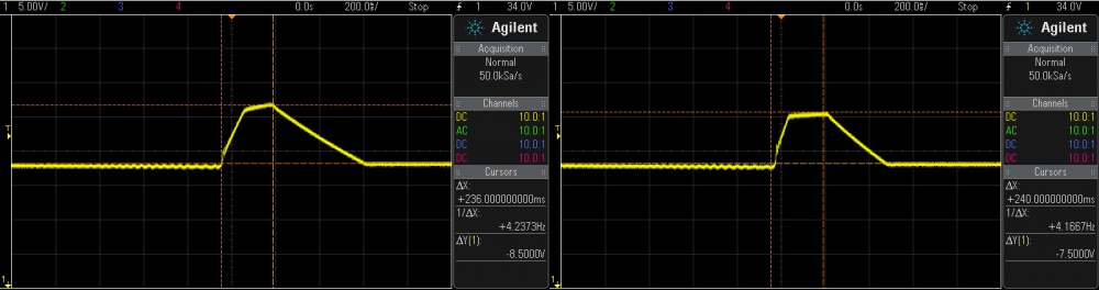
As you can see, in both cases, the voltage peaks at around 38V, at which point the TVS kicks in. Within 0.4s, the spike has dissipated and the voltage is back to normal. Pretty impressive for such a little circuit element. But of course, it has its own limitations as well. If the voltage spike is too long or too high, it will heat up too fast and simply melt. If you choose to put several TVS diodes in series, you can spread the heat dissipation across all elements.
This video shows the the TVS diode dissipating the voltage spike as heat. With a single diode, the temperature reaches 34°C, and with three, they reach about 30°C. This particular diode is rated to 175°C, so it should be sufficient to protect the motor controller when driving this motor and load.