Voltage Output Guide: Difference between revisions
No edit summary |
No edit summary |
||
| (11 intermediate revisions by 4 users not shown) | |||
| Line 1: | Line 1: | ||
<metadesc>Voltage outputs are useful for controlling motors and other analog devices. Find voltage output boards that connect via USB at Phidgets.com.</metadesc> | |||
[[Category: Primer]] | [[Category: Primer]] | ||
__TOC__ | __TOC__ | ||
==Introduction== | ==Introduction== | ||
A voltage output is simply an interface that takes digital data and outputs it in the form of a voltage signal. Since this type of output is meant to generate signals, it is usually low current (20mA or less) and low voltage (10V DC or less). The current can't be controlled, so this output is only suitable for interfacing with devices that accept voltage signals. | |||
Voltage outputs are commonly used for generating simple waveforms for test purposes, employing dimmer control on low-current electronics, or controlling devices such as [[Solid State Relay Primer#Proportional_Control_SSR|proportional control relays]]. | |||
==Technical Explanation== | ==Technical Explanation== | ||
===How it works=== | ===How it works=== | ||
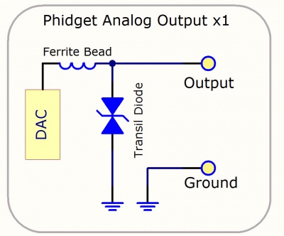
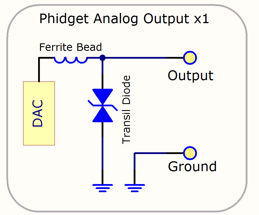
[[File:Analog_Out_Diagram.jpg|link=|thumb|400px|A simplified schematic of a Phidgets Inc. Voltage Output.<br>[[Media:Analog_Out_Diagram.jpg|Full-Sized Image]]]] | |||
When the user selects an output value in software, the digital-to-analog converter (DAC) on the board converts this digital value into an analog voltage signal. The resulting signal is filtered through a ferrite bead, and reaches the output on the terminal block. The transil diode protects the voltage outputs from electrostatic discharge. | |||
When the user selects an output value in software, the digital-to-analog converter (DAC) on the board converts this digital value into an analog voltage signal. The resulting signal is filtered through a ferrite bead, and reaches the output on the terminal block. The transil diode protects the | |||
<br clear=all> | <br clear=all> | ||
===Basic Use=== | ===Basic Use=== | ||
To use a voltage output, simply connect the output terminals to the device you want to supply a signal to. Make sure that the device is specified to draw less current than the specified maximum current per channel of the voltage output Phidget (found in the specification table on the Phidget's product page). If you exceed the maximum current of a Phidget voltage output, an over-current error will be thrown, because passing the current limit will cause the output voltage to drop depending on the resistance of the load according to Ohm's law. For an example of this, the [[OUT1000_User_Guide#Technical_Details|technical section]] of the OUT1000 User Guide has a graph that plots this voltage drop. Due to the difficulty in predicting the precise amount of voltage drop, it's a good idea to stay as far from the current limit as your application will allow. | |||
If you need to generate a voltage signal with a higher current limit, you can build a simple amplifier circuit between the voltage output and the load. | |||
If you | ===Avoiding Startup Transients=== | ||
When a voltage output board is first powered up, the voltage level on the output will be unpredictable for a few milliseconds. If this behaviour is causing problems for your system, you may want to put a [[Solid State Relay Primer|relay]] on the output and write your program to switch the relay on after an appropriate amount of time has elapsed after startup. For output boards that support multiple range settings, this method could also be used to avoid transient behaviour when switching the range setting. | |||
Revision as of 17:00, 29 November 2017
Introduction
A voltage output is simply an interface that takes digital data and outputs it in the form of a voltage signal. Since this type of output is meant to generate signals, it is usually low current (20mA or less) and low voltage (10V DC or less). The current can't be controlled, so this output is only suitable for interfacing with devices that accept voltage signals.
Voltage outputs are commonly used for generating simple waveforms for test purposes, employing dimmer control on low-current electronics, or controlling devices such as proportional control relays.
Technical Explanation
How it works
When the user selects an output value in software, the digital-to-analog converter (DAC) on the board converts this digital value into an analog voltage signal. The resulting signal is filtered through a ferrite bead, and reaches the output on the terminal block. The transil diode protects the voltage outputs from electrostatic discharge.
Basic Use
To use a voltage output, simply connect the output terminals to the device you want to supply a signal to. Make sure that the device is specified to draw less current than the specified maximum current per channel of the voltage output Phidget (found in the specification table on the Phidget's product page). If you exceed the maximum current of a Phidget voltage output, an over-current error will be thrown, because passing the current limit will cause the output voltage to drop depending on the resistance of the load according to Ohm's law. For an example of this, the technical section of the OUT1000 User Guide has a graph that plots this voltage drop. Due to the difficulty in predicting the precise amount of voltage drop, it's a good idea to stay as far from the current limit as your application will allow.
If you need to generate a voltage signal with a higher current limit, you can build a simple amplifier circuit between the voltage output and the load.
Avoiding Startup Transients
When a voltage output board is first powered up, the voltage level on the output will be unpredictable for a few milliseconds. If this behaviour is causing problems for your system, you may want to put a relay on the output and write your program to switch the relay on after an appropriate amount of time has elapsed after startup. For output boards that support multiple range settings, this method could also be used to avoid transient behaviour when switching the range setting.