Mechanical Relay Guide: Difference between revisions
No edit summary |
|||
| (25 intermediate revisions by 4 users not shown) | |||
| Line 1: | Line 1: | ||
<metadesc>Mechanical relays can switch a power or signal line by physically moving metal contacts with an electromagnet. Learn more at Phidgets.com.</metadesc> | |||
[[Category: Primer]] | [[Category: Primer]] | ||
__TOC__ | |||
==Introduction== | ==Introduction== | ||
Mechanical relays are devices that can turn on or turn off the power supplied to another device, like a switch. However, instead of having a person flip the switch, mechanical relays switch when provided with a small amount of power. This allows high-power circuits to be controlled by low-power devices. | |||
Mechanical relays are devices that can turn on or turn off the power supplied to another device, like a switch. However, instead of having a person flip the switch, mechanical relays switch when provided with a small amount of power. This allows high-power circuits to be controlled by low-power devices. | |||
They perform the same function as [[Solid State Relay Primer|Solid State Relays]], except they are less expensive and have a shorter lifespan. | They perform the same function as [[Solid State Relay Primer|Solid State Relays]], except they are less expensive and have a shorter lifespan. | ||
You can use them to control [[LED Primer|LEDs]], heaters, appliances, and generally any powered device as long as the power you're switching falls within the limits of the relay you're using. | You can use them to control [[LED Primer|LEDs]], heaters, appliances, and generally any powered device as long as the power you're switching falls within the limits of the relay you're using. | ||
[[File:1017.jpg|link=|center|400px]] | |||
= | We sell boards with multiple relays on them (such as the [{{SERVER}}/products.php?product_id=1017 1017], shown above), making it easy to control many separate circuits with your computer. Some boards, like the 1017, plug straight into your USB port, while others are designed to connect to another device, such as the digital outputs of an [[InterfaceKit Digital Outputs|Interface Kit]] or {{VINTHub}}. | ||
==How it works== | |||
[[File:Mechanical_relay.jpg|thumb|link=|500px|'''Mechanical Relay'''<br />The switching arm and contacts of a mechanical relay.]] | |||
Mechanical relays use an electromagnetic coil to open or close the circuit. When current runs through the input and energizes the coil, it creates a small magnetic field which either pulls the arm of the switch away from the other contact of the switch, or pushes it down to close the switch depending on the how the switch is made. A relay also serves as an isolator, because the control (input) and load (output) ends of the relay are not electrically connected. This allows you to protect the device you're using to control the relay from power surges in your application. | Mechanical relays use an electromagnetic coil to open or close the circuit. When current runs through the input and energizes the coil, it creates a small magnetic field which either pulls the arm of the switch away from the other contact of the switch, or pushes it down to close the switch depending on the how the switch is made. A relay also serves as an isolator, because the control (input) and load (output) ends of the relay are not electrically connected. This allows you to protect the device you're using to control the relay from power surges in your application. | ||
===Basic Use=== | ===Basic Use=== | ||
Controlling a mechanical relay is as easy as turning on an LED or light bulb. By simply supplying enough power to energize the electromagnetic coil, you will be able to control a mechanical relay. A normal digital output will not be powerful enough without external components as described in the [[InterfaceKit Digital Outputs#Controlling a Relay with a N-Channel MOSFET| relay section of the Digital Output Primer]]. A Phidget with open collector digital outputs, (such as the [{{SERVER}}/?tier=3&catid=46&pcid=39&prodid=720 REL1100] or [{{SERVER}}/?tier=3&catid=46&pcid=39&prodid=721 REL1101]), on the other hand, will be able to control a relay on its own. | |||
Controlling a mechanical relay is as easy as turning on an LED or light bulb. By simply supplying enough power to energize the electromagnetic coil, you will be able to control a mechanical relay. A normal digital output will not be powerful enough without external components as described in the [[Digital | |||
Relays are often used in large quantities to turn multiple devices on and off in a particular order or timing. For example, a popular trend has been to hook up many strands of Christmas lights to multiple relays and a control system in order to make them flash in rhythm with specific music. | Relays are often used in large quantities to turn multiple devices on and off in a particular order or timing. For example, a popular trend has been to hook up many strands of Christmas lights to multiple relays and a control system in order to make them flash in rhythm with specific music. | ||
Relays are designed to be controlled by a particular voltage applied to the coil. If you buy a relay product from | Relays are designed to be controlled by a particular voltage applied to the coil. If you buy a relay product from us, this is taken care of for you. You will be able to switch the relays via USB with the Digital Outputs on a [[InterfaceKit Digital Outputs|Phidget InterfaceKit]] or {{VINTHub}}. If you are integrating your own relay, you'll want to keep an eye on the specifications. The relay coil is also specified for a particular current. For example, a 5V relay might require 70mA. If you connect this relay to a very weak source of 5V, like a digital output, the output will not be able to provide 70mA, and there will not be enough current to switch the relay. | ||
( | The load side of the relay also requires a minimum current. This minimum load current (also called "wetting current") is a requirement because the electricity needs to conduct through an oxide layer that forms on the contacts of the relay. If the minimum load current requirement of your relay is too high, you won't be able to use it to switch a signal (such as the data line on an analog sensor), you'll only be able to switch power to a circuit. If you're using a relay to switch a signal, [[#Contact Bounce|contact bounce]] might also be a problem. | ||
====Switching Speed and High-Frequency Switching==== | |||
Even though they use moving mechanical parts, mechanical relays switch very quickly. The amount of time it takes for current to begin flowing through the circuit from when the relay's input is activated is in the order of tens of milliseconds. For extremely time-sensitive applications that need to minimize switching delay, [[Solid State Relay Primer|Solid State Relays]] can switch as quickly as 1ms. | |||
You should be careful when using mechanical relays in applications that require very frequent switching. Typically, mechanical relays can only manage one contact every few seconds- any quicker and they may begin to overheat. | |||
===Safety=== | |||
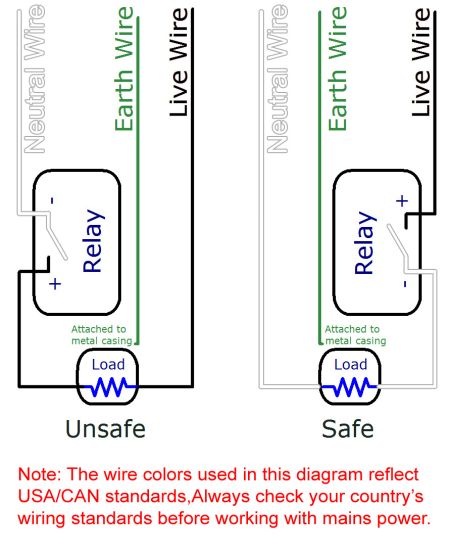
[[File:relay_safety.jpg|thumb|450px|link=|Two circuit diagrams showing the improper and proper ways of switching mains electricity with a relay.<br />]] | |||
Since relays switch high currents and voltages, standard electricity safety precautions apply. Make sure you never touch the terminals while the relay is powered. | |||
When placing a relay in a circuit, it is always a good idea to put it between the power supply and the load, especially when using higher voltages. If the relay is instead placed between the load and ground, the circuit will still work the same, but when the relay is open, the load will still be directly connected to the power supply. This could cause safety concerns because someone might touch the terminals on the load, thinking it's safe because the device appears to be off. If the electricity finds a path to ground through their body, they will be electrocuted. If the relay is placed between the power supply and the ground, electrocution would only be a risk if the live terminal on the relay is touched. Again, the relay terminals should always be properly covered to avoid the risk of electrocution. | |||
When an mechanical relay fails, it often fails permanently closed. This is because the contacts can actually weld to each other. See the section on [[#Arcing, Interference, and Sticking|Arcing, Interference, and Sticking]] for more information. | |||
This means that as long as the power supply remains on, the load will be powered, possibly creating a fire or safety hazard. | |||
<br clear=all> | |||
==Choosing a Relay== | ==Choosing a Relay== | ||
Since mechanical relays are nothing more than a controllable switch, they support both AC and DC loads. | Since mechanical relays are nothing more than a controllable switch, they support both AC and DC loads. | ||
| Line 65: | Line 52: | ||
===Switch Type=== | ===Switch Type=== | ||
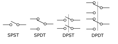
One of the major characteristics of a mechanical relay is the design of the switch inside. A switch can generally be defined by the number of '''poles''' and '''throws''' it has. The number of "poles" refers to the number of individual circuits the switch controls. The number of "throws" refers to the number of positions the switch arm can occupy. | One of the major characteristics of a mechanical relay is the design of the switch inside. A switch can generally be defined by the number of '''poles''' and '''throws''' it has. The number of "poles" refers to the number of individual circuits the switch controls. The number of "throws" refers to the number of positions the switch arm can occupy. | ||
[[File:Switch_types.jpg|border| | [[File:Switch_types.jpg|border|400px|link=|center]] | ||
====Single Pole, Single Throw (SPST)==== | ====Single Pole, Single Throw (SPST)==== | ||
This is a simple switch with only one path for the current to follow. The relay is either designed to be '''normally open (NO)''' or '''normally closed (NC)'''. If it is normally open, the arm of the switch is held away from the contact with a spring when the relay is off and the electromagnet pulls the arm to make contact and close the switch when the relay is turned on. If it is normally closed, the arm of the switch is held to the contact when the relay is off, and the electromagnet pulls the arm away when the relay is turned on. | |||
This is a simple switch with only one path for the current to follow. The relay is either designed to be '''normally open''' or '''normally closed'''. If it is normally open, the arm of the switch is held away from the contact with a spring when the relay is off and the electromagnet pulls the arm to make contact and close the switch when the relay is turned on. If it is normally closed, the arm of the switch is held to the contact when the relay is off, and the electromagnet pulls the arm away when the relay is turned on. | |||
While the decision to use a normally opened or normally closed relay may seem arbitrary at first, it is actually very important for certain applications. If you choose a normally closed relay, it means your load will remain powered as long as the relay coil is '''not''' powered. If some other part of your system fails, causing your relay to lose power, your load will remain powered even though it should not be. For loads that are potentially dangerous when left on (such as a heater, or a high-power load) it is best to use a normally open relay, so that in the event of a system failure, the load will remain off. On the other hand, circuits that are designed to be powered most of the time but temporarily interrupted will use less power if they use a normally closed relay. An example of this type of circuit is the radio in a car: When the engine is started, the radio circuit is momentarily switched off because the engine needs a large amount of battery power to start. | While the decision to use a normally opened or normally closed relay may seem arbitrary at first, it is actually very important for certain applications. If you choose a normally closed relay, it means your load will remain powered as long as the relay coil is '''not''' powered. If some other part of your system fails, causing your relay to lose power, your load will remain powered even though it should not be. For loads that are potentially dangerous when left on (such as a heater, or a high-power load) it is best to use a normally open relay, so that in the event of a system failure, the load will remain off. On the other hand, circuits that are designed to be powered most of the time but temporarily interrupted will use less power if they use a normally closed relay. An example of this type of circuit is the radio in a car: When the engine is started, the radio circuit is momentarily switched off because the engine needs a large amount of battery power to start. | ||
====Single Pole, Double Throw (SPDT)==== | ====Single Pole, Double Throw (SPDT)==== | ||
[[File:relay2loads.png|thumb|link=|300px|'''Toggle Between Two Loads'''<br />By connecting the power supply to the common terminal, and connecting a different load to the other two terminals, a relay with a SPDT switch can be used to toggle power between the two loads.<br />[[Media:relay2loads.png|Full-size Image]]]] | [[File:relay2loads.png|thumb|link=|300px|'''Toggle Between Two Loads'''<br />By connecting the power supply to the common terminal, and connecting a different load to the other two terminals, a relay with a SPDT switch can be used to toggle power between the two loads.<br />[[Media:relay2loads.png|Full-size Image]]]] | ||
| Line 85: | Line 69: | ||
====Double Pole, Single Throw (DPST)==== | ====Double Pole, Single Throw (DPST)==== | ||
This switch functions like two SPST switches, but both switches are controlled by one coil. This type of switch is useful for keeping two loads on separate circuits while still being able to have them turn on and off in unison. | This switch functions like two SPST switches, but both switches are controlled by one coil. This type of switch is useful for keeping two loads on separate circuits while still being able to have them turn on and off in unison. | ||
====Double Pole, Double Throw (DPDT)==== | ====Double Pole, Double Throw (DPDT)==== | ||
This switch functions the same as a SPDT switch, except there are two of them, but are both controlled by a single input on the relay. You can use this type of switch to simultaneously control two separate circuits. | This switch functions the same as a SPDT switch, except there are two of them, but are both controlled by a single input on the relay. You can use this type of switch to simultaneously control two separate circuits. | ||
==Troubleshooting== | ==Troubleshooting== | ||
===Contact Bounce=== | ===Contact Bounce=== | ||
As with any mechanical switch, relays are susceptible to contact bounce. This means that when the switch closes, the arm can bounce on the contact, causing the load's power to flicker slightly. This usually only matters when the application is triggered by pulses in the power signal, or for applications where meaningful data is being switched instead of power. For example, a circuit designed to increment a counter every time power is applied to its input could incorrectly interpret a bouncing relay contact as multiple switch events. Or, a circuit that uses a relay to switch an audio signal between two different paths will experience some static noise when switching if there is significant contact bounce. It's worth mentioning that [[Solid State Relay Primer|Solid State Relays]] don't suffer from contact bounce, because they operate without using moving mechanical parts. | |||
As with any mechanical switch, relays are susceptible to | |||
===Arcing, Interference, and Sticking=== | ===Arcing, Interference, and Sticking=== | ||
[[File:contact_arc.jpg|border|link=|center]] | |||
[[File:contact_arc.jpg|border|link=]] | |||
When a mechanical relay opens or closes, for the moment that the arm of the switch is very close (but not connected) to the contact, the electric current can arc through the air between the contacts. | When a mechanical relay opens or closes, for the moment that the arm of the switch is very close (but not connected) to the contact, the electric current can arc through the air between the contacts. | ||
This arc can cause interference with nearby electrical instruments and sensors. For example, if an unshielded cable carrying an audio signal is travelling past some relays whose contacts are arcing when they switch, the audio would contain bursts of static noise. | This arc can cause interference with nearby electrical instruments and sensors. For example, if an unshielded cable carrying an audio signal is travelling past some relays whose contacts are arcing when they switch, the audio would contain bursts of static noise. | ||
| Line 109: | Line 88: | ||
===Prolonging Relay Lifespan=== | ===Prolonging Relay Lifespan=== | ||
In order to prolong the lifespan of your relay, avoid switching loads of higher voltage or current than the relay is built for, and avoid highly inductive loads, which worsen the effects of contact arcing. Your Load will probably be inductive if it is built around a large coil of wire - motors and transformers are typical examples. A load considered resistive may also have loops of wire - for instance, hair dryers, toasters, incandescent bulbs use twisted wire elements to generate the heat. An inductive load will have thousands of loops of wire - it's a matter of scale. | |||
Additionally, you should avoid switching at or near the relay's maximum frequency if possible. You can think of a mechanical relay's lifespan in terms of number times switched rather than the amount of time it's used for. A relay that doesn't need to be switched very often can last a long time. If your application requires constant switching over long periods of time, it might be more cost-effective to use a [[Solid State Relay Primer|Solid State Relay]]. | |||
Additionally, you should avoid | |||
====Arc Suppression ==== | ====Arc Suppression ==== | ||
[[File:Mechanical_relay_diode.jpg|link=|thumb|300px|'''DC Load Protection'''<br/>A diagram of a mechanical relay switching a DC load. An optional diode and fuse are used to protect the relay and prevent hardware damaged caused by improper wiring.<br/>[[Media:Mechanical_relay_diode.jpg|Full-sized Image]]]] | [[File:Mechanical_relay_diode.jpg|link=|thumb|300px|'''DC Load Protection'''<br/>A diagram of a mechanical relay switching a DC load. An optional diode and fuse are used to protect the relay and prevent hardware damaged caused by improper wiring.<br/>[[Media:Mechanical_relay_diode.jpg|Full-sized Image]]]] | ||
[[File:Mechanical_relay_mov.jpg|link=|thumb|300px|'''AC Load Protection'''<br/>A diagram of a mechanical relay switching an AC load. An optional MOV or Transil diode is placed in parallel to protect the relay from voltage spikes.<br/>[[Media:Mechanical_relay_mov.jpg|Full-Sized Image]]]] | [[File:Mechanical_relay_mov.jpg|link=|thumb|300px|'''AC Load Protection'''<br/>A diagram of a mechanical relay switching an AC load. An optional MOV or Transil diode is placed in parallel to protect the relay from voltage spikes.<br/>[[Media:Mechanical_relay_mov.jpg|Full-Sized Image]]]] | ||
The main cause of failure for mechanical relays is electricity arcing across the contacts during switching. To lengthen the lifespan of your relay, you can add various circuit elements that mitigate arcing. | The main cause of failure for mechanical relays is electricity arcing across the contacts during switching. To lengthen the lifespan of your relay, you can add various circuit elements that mitigate arcing. | ||
For DC powered applications, one simple method of mitigating the effects of contact arcing is to place a feedback diode across the load, as pictured. This will allow some of the residual electricity in the circuit to recirculate through the load instead of contributing to the arc that forms when the switch makes the transition from closed to open. You can buy a suitable diode from any electronics distributor, like this [http:// | For DC powered applications, one simple method of mitigating the effects of contact arcing is to place a feedback diode across the load, as pictured. This will allow some of the residual electricity in the circuit to recirculate through the load instead of contributing to the arc that forms when the switch makes the transition from closed to open. You can buy a suitable diode from any electronics distributor, like this [http://www.digikey.com/product-search/en/discrete-semiconductor-products/diodes-rectifiers-single/1376383?k=10a02 Diode] from Digikey. | ||
For AC powered applications, you can put a Metal Oxide Varistor (MOV) across the load terminals of the relay in order to protect it from voltage spikes. An MOV will not remove the entire arc, but it will be helpful in circuits up to several hundred volts. You can buy an MOV from any electronics distributor, like this [http:// | For AC powered applications, you can put a Metal Oxide Varistor (MOV) across the load terminals of the relay in order to protect it from voltage spikes. An MOV will not remove the entire arc, but it will be helpful in circuits up to several hundred volts. You can buy an MOV from any electronics distributor, like this [http://www.digikey.com/scripts/dksearch/dksus.dll?keywords=tmov20rp200e MOV] from Digikey. | ||
For low-voltage AC applications, a bi-directional transient voltage suppression diode ("transil diode") that is rated for higher than the AC voltage of the circuit can be placed across the relay terminals in order to protect it from voltage spikes. You can buy one from any electronics distributor, like this [http:// | For low-voltage AC applications, a bi-directional transient voltage suppression diode ("transil diode") that is rated for higher than the AC voltage of the circuit can be placed across the relay terminals in order to protect it from voltage spikes. You can buy one from any electronics distributor, like this [http://www.digikey.com/scripts/dksearch/dksus.dll?keywords=p6ke47carl Transil Diode] from Digikey. | ||
<br clear="all"> | <br clear="all"> | ||
| Line 131: | Line 108: | ||
Mechanical relays are inexpensive and simple devices that allow AC or DC circuits to be switched on and off using a small amount of power. | Mechanical relays are inexpensive and simple devices that allow AC or DC circuits to be switched on and off using a small amount of power. | ||
They come in a variety of switch formats, enabling the user to build some very clever control into a circuit. Phidgets Inc. sells boards with multiple relays that can be connected directly to USB, so they can be controlled by your program. | They come in a variety of switch formats, enabling the user to build some very clever control into a circuit. Phidgets Inc. sells boards with multiple relays that can be connected directly to USB, or indirectly through a {{VINTHub}} so they can be controlled by your program. | ||
Contact arcing and switch bounce can be an obstacle for some applications, but both are common problems and can be worked around fairly easily. | Contact arcing and switch bounce can be an obstacle for some applications, but both are common problems and can be worked around fairly easily. | ||
Mechanical relays don't last as long as solid state relays, but if you take care of them, they can be a good cost-effective alternative. | Mechanical relays don't last as long as solid state relays, but if you take care of them, they can be a good cost-effective alternative. | ||
Revision as of 16:55, 29 November 2017
Introduction
Mechanical relays are devices that can turn on or turn off the power supplied to another device, like a switch. However, instead of having a person flip the switch, mechanical relays switch when provided with a small amount of power. This allows high-power circuits to be controlled by low-power devices.
They perform the same function as Solid State Relays, except they are less expensive and have a shorter lifespan. You can use them to control LEDs, heaters, appliances, and generally any powered device as long as the power you're switching falls within the limits of the relay you're using.
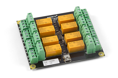
We sell boards with multiple relays on them (such as the 1017, shown above), making it easy to control many separate circuits with your computer. Some boards, like the 1017, plug straight into your USB port, while others are designed to connect to another device, such as the digital outputs of an Interface Kit or VINT Hub.
How it works
Mechanical relays use an electromagnetic coil to open or close the circuit. When current runs through the input and energizes the coil, it creates a small magnetic field which either pulls the arm of the switch away from the other contact of the switch, or pushes it down to close the switch depending on the how the switch is made. A relay also serves as an isolator, because the control (input) and load (output) ends of the relay are not electrically connected. This allows you to protect the device you're using to control the relay from power surges in your application.
Basic Use
Controlling a mechanical relay is as easy as turning on an LED or light bulb. By simply supplying enough power to energize the electromagnetic coil, you will be able to control a mechanical relay. A normal digital output will not be powerful enough without external components as described in the relay section of the Digital Output Primer. A Phidget with open collector digital outputs, (such as the REL1100 or REL1101), on the other hand, will be able to control a relay on its own. Relays are often used in large quantities to turn multiple devices on and off in a particular order or timing. For example, a popular trend has been to hook up many strands of Christmas lights to multiple relays and a control system in order to make them flash in rhythm with specific music.
Relays are designed to be controlled by a particular voltage applied to the coil. If you buy a relay product from us, this is taken care of for you. You will be able to switch the relays via USB with the Digital Outputs on a Phidget InterfaceKit or VINT Hub. If you are integrating your own relay, you'll want to keep an eye on the specifications. The relay coil is also specified for a particular current. For example, a 5V relay might require 70mA. If you connect this relay to a very weak source of 5V, like a digital output, the output will not be able to provide 70mA, and there will not be enough current to switch the relay.
The load side of the relay also requires a minimum current. This minimum load current (also called "wetting current") is a requirement because the electricity needs to conduct through an oxide layer that forms on the contacts of the relay. If the minimum load current requirement of your relay is too high, you won't be able to use it to switch a signal (such as the data line on an analog sensor), you'll only be able to switch power to a circuit. If you're using a relay to switch a signal, contact bounce might also be a problem.
Switching Speed and High-Frequency Switching
Even though they use moving mechanical parts, mechanical relays switch very quickly. The amount of time it takes for current to begin flowing through the circuit from when the relay's input is activated is in the order of tens of milliseconds. For extremely time-sensitive applications that need to minimize switching delay, Solid State Relays can switch as quickly as 1ms.
You should be careful when using mechanical relays in applications that require very frequent switching. Typically, mechanical relays can only manage one contact every few seconds- any quicker and they may begin to overheat.
Safety
Since relays switch high currents and voltages, standard electricity safety precautions apply. Make sure you never touch the terminals while the relay is powered.
When placing a relay in a circuit, it is always a good idea to put it between the power supply and the load, especially when using higher voltages. If the relay is instead placed between the load and ground, the circuit will still work the same, but when the relay is open, the load will still be directly connected to the power supply. This could cause safety concerns because someone might touch the terminals on the load, thinking it's safe because the device appears to be off. If the electricity finds a path to ground through their body, they will be electrocuted. If the relay is placed between the power supply and the ground, electrocution would only be a risk if the live terminal on the relay is touched. Again, the relay terminals should always be properly covered to avoid the risk of electrocution.
When an mechanical relay fails, it often fails permanently closed. This is because the contacts can actually weld to each other. See the section on Arcing, Interference, and Sticking for more information. This means that as long as the power supply remains on, the load will be powered, possibly creating a fire or safety hazard.
Choosing a Relay
Since mechanical relays are nothing more than a controllable switch, they support both AC and DC loads.
The major deciding factor in choosing a mechanical relay is the amount of current it's capable of switching. For example, the most current you can switch with the largest mechanical relay we sell is 5A DC or 10A AC. If the load you're switching consumes more current than our mechanical relays can handle, take a look at our Solid State Relays.
Switch Type
One of the major characteristics of a mechanical relay is the design of the switch inside. A switch can generally be defined by the number of poles and throws it has. The number of "poles" refers to the number of individual circuits the switch controls. The number of "throws" refers to the number of positions the switch arm can occupy.
Single Pole, Single Throw (SPST)
This is a simple switch with only one path for the current to follow. The relay is either designed to be normally open (NO) or normally closed (NC). If it is normally open, the arm of the switch is held away from the contact with a spring when the relay is off and the electromagnet pulls the arm to make contact and close the switch when the relay is turned on. If it is normally closed, the arm of the switch is held to the contact when the relay is off, and the electromagnet pulls the arm away when the relay is turned on.
While the decision to use a normally opened or normally closed relay may seem arbitrary at first, it is actually very important for certain applications. If you choose a normally closed relay, it means your load will remain powered as long as the relay coil is not powered. If some other part of your system fails, causing your relay to lose power, your load will remain powered even though it should not be. For loads that are potentially dangerous when left on (such as a heater, or a high-power load) it is best to use a normally open relay, so that in the event of a system failure, the load will remain off. On the other hand, circuits that are designed to be powered most of the time but temporarily interrupted will use less power if they use a normally closed relay. An example of this type of circuit is the radio in a car: When the engine is started, the radio circuit is momentarily switched off because the engine needs a large amount of battery power to start.
Single Pole, Double Throw (SPDT)
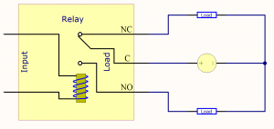
By connecting the power supply to the common terminal, and connecting a different load to the other two terminals, a relay with a SPDT switch can be used to toggle power between the two loads.
Full-size Image
This switch has two paths for the current to follow. This type of relay is useful if you want to toggle power between two different loads, as pictured. You can also use a SPDT relay as a single pole, single throw switch, and it can function as normally open or normally closed depending on which pins (common and normally open, or common and normally closed) you connect the load to.
Double Pole, Single Throw (DPST)
This switch functions like two SPST switches, but both switches are controlled by one coil. This type of switch is useful for keeping two loads on separate circuits while still being able to have them turn on and off in unison.
Double Pole, Double Throw (DPDT)
This switch functions the same as a SPDT switch, except there are two of them, but are both controlled by a single input on the relay. You can use this type of switch to simultaneously control two separate circuits.
Troubleshooting
Contact Bounce
As with any mechanical switch, relays are susceptible to contact bounce. This means that when the switch closes, the arm can bounce on the contact, causing the load's power to flicker slightly. This usually only matters when the application is triggered by pulses in the power signal, or for applications where meaningful data is being switched instead of power. For example, a circuit designed to increment a counter every time power is applied to its input could incorrectly interpret a bouncing relay contact as multiple switch events. Or, a circuit that uses a relay to switch an audio signal between two different paths will experience some static noise when switching if there is significant contact bounce. It's worth mentioning that Solid State Relays don't suffer from contact bounce, because they operate without using moving mechanical parts.
Arcing, Interference, and Sticking
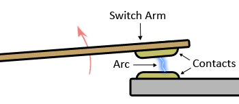
When a mechanical relay opens or closes, for the moment that the arm of the switch is very close (but not connected) to the contact, the electric current can arc through the air between the contacts. This arc can cause interference with nearby electrical instruments and sensors. For example, if an unshielded cable carrying an audio signal is travelling past some relays whose contacts are arcing when they switch, the audio would contain bursts of static noise.
This arcing can also heat up the contacts of the switch enough that they can slowly degrade away until the relay no longer functions. They could also weld together, causing the relay to stay on permanently, which means your load will be powered constantly. If this imposes safety concerns, you should install a fail-safe of some kind. For example, some sauna heaters are turned on with a mechanical relay. In the event of a relay failure, the sauna heater will remain on and continue heating the room beyond the intended temperature. However, a simple mechanical temperature sensor is installed which cuts power to the heater if the room goes beyond a certain temperature.
Some relays are encased in a clear plastic enclosure (sometimes called "ice cube" relays), so the switch contacts can be easily inspected. By inspecting the contacts periodically, you could tell when the relay is getting near the end of its life.
Prolonging Relay Lifespan
In order to prolong the lifespan of your relay, avoid switching loads of higher voltage or current than the relay is built for, and avoid highly inductive loads, which worsen the effects of contact arcing. Your Load will probably be inductive if it is built around a large coil of wire - motors and transformers are typical examples. A load considered resistive may also have loops of wire - for instance, hair dryers, toasters, incandescent bulbs use twisted wire elements to generate the heat. An inductive load will have thousands of loops of wire - it's a matter of scale.
Additionally, you should avoid switching at or near the relay's maximum frequency if possible. You can think of a mechanical relay's lifespan in terms of number times switched rather than the amount of time it's used for. A relay that doesn't need to be switched very often can last a long time. If your application requires constant switching over long periods of time, it might be more cost-effective to use a Solid State Relay.
Arc Suppression
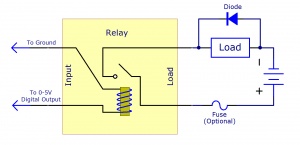
A diagram of a mechanical relay switching a DC load. An optional diode and fuse are used to protect the relay and prevent hardware damaged caused by improper wiring.
Full-sized Image
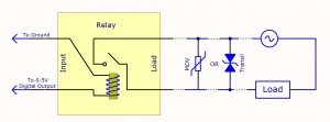
A diagram of a mechanical relay switching an AC load. An optional MOV or Transil diode is placed in parallel to protect the relay from voltage spikes.
Full-Sized Image
The main cause of failure for mechanical relays is electricity arcing across the contacts during switching. To lengthen the lifespan of your relay, you can add various circuit elements that mitigate arcing.
For DC powered applications, one simple method of mitigating the effects of contact arcing is to place a feedback diode across the load, as pictured. This will allow some of the residual electricity in the circuit to recirculate through the load instead of contributing to the arc that forms when the switch makes the transition from closed to open. You can buy a suitable diode from any electronics distributor, like this Diode from Digikey.
For AC powered applications, you can put a Metal Oxide Varistor (MOV) across the load terminals of the relay in order to protect it from voltage spikes. An MOV will not remove the entire arc, but it will be helpful in circuits up to several hundred volts. You can buy an MOV from any electronics distributor, like this MOV from Digikey.
For low-voltage AC applications, a bi-directional transient voltage suppression diode ("transil diode") that is rated for higher than the AC voltage of the circuit can be placed across the relay terminals in order to protect it from voltage spikes. You can buy one from any electronics distributor, like this Transil Diode from Digikey.
Conclusion
Mechanical relays are inexpensive and simple devices that allow AC or DC circuits to be switched on and off using a small amount of power. They come in a variety of switch formats, enabling the user to build some very clever control into a circuit. Phidgets Inc. sells boards with multiple relays that can be connected directly to USB, or indirectly through a VINT Hub so they can be controlled by your program.
Contact arcing and switch bounce can be an obstacle for some applications, but both are common problems and can be worked around fairly easily. Mechanical relays don't last as long as solid state relays, but if you take care of them, they can be a good cost-effective alternative.

