DAQ1400 User Guide
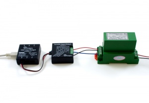
Required Hardware
- A DAQ1400 Versatile Input Phidget
- A VINT Hub
- A 3-wire Phidget cable
- A USB cable
- A computer
- Sensors or devices to test the various inputs of the DAQ1400
Connecting the Pieces
- Connect the DAQ1400 to the VINT Hub using the Phidget cable.
- Connect the VINT Hub to your computer with a USB cable.
- Connect sensor or device to the DAQ1400's appropriate inputs. For details, see the technical section.
Testing Using Windows
Phidget Control Panel
In order to demonstrate the functionality of the DAQ1400, the Phidget Control Panel running on a Windows machine will be used.
The Phidget Control Panel is available for use on both macOS and Windows machines.
Windows
To open the Phidget Control Panel on Windows, find the ![]() icon in the taskbar. If it is not there, open up the start menu and search for Phidget Control Panel
icon in the taskbar. If it is not there, open up the start menu and search for Phidget Control Panel
macOS
To open the Phidget Control Panel on macOS, open Finder and navigate to the Phidget Control Panel in the Applications list. Double click on the ![]() icon to bring up the Phidget Control Panel.
icon to bring up the Phidget Control Panel.
For more information, take a look at the getting started guide for your operating system:
Linux users can follow the getting started with Linux guide and continue reading here for more information about the DAQ1400.
First Look
After plugging the DAQ1400 into your computer and opening the Phidget Control Panel, you will see something like this:
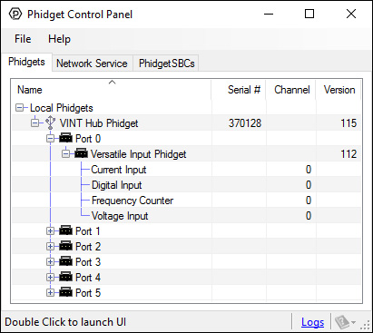
The Phidget Control Panel will list all connected Phidgets and associated objects, as well as the following information:
- Serial number: allows you to differentiate between similar Phidgets.
- Channel: allows you to differentiate between similar objects on a Phidget.
- Version number: corresponds to the firmware version your Phidget is running. If your Phidget is listed in red, your firmware is out of date. Update the firmware by double-clicking the entry.
The Phidget Control Panel can also be used to test your device. Double-clicking on an object will open an example.
Voltage Input
Double-click on the Voltage Input object {{{2}}} in order to run the example: [[Image:{{{1}}}_VoltageInput_Example.jpg|center|link=]]
General information about the selected object will be displayed at the top of the window. You can also experiment with the following functionality:
- Modify the change trigger and/or data interval value by dragging the sliders. For more information on these settings, see the data interval/change trigger page.
Current Input
Double-click on the Current Input object {{{2}}} in order to run the example: [[Image:{{{1}}}_CurrentInput_Example.jpg|center|link=]]
General information about the selected object will be displayed at the top of the window. You can also experiment with the following functionality:
- Modify the change trigger and/or data interval value by dragging the sliders. For more information on these settings, see the data interval/change trigger page.
Digital Input
[[Image:{{{1}}}_DigitalInput_Example.jpg|right|link=]]
When you double click on an Digital Input object, a window like the one pictured will open.
- At the top of the window, information about your device and the properties of this particular channel will be listed.
- In the middle, there is a box that will display "true" or "false" depending on the state of the digital input. Be sure you select the proper mode (NPN / PNP) for your particular sensor. If you have a switch, you can test this input by connecting the digital input terminal of the sensor to one of the switch's terminals, and the sensor's ground terminal to another. Pressing the switch should cause the input to read "true".
- At the bottom of the window, there is a selection for the power supply. The power supply setting must be set to the voltage expected by the sensor connected to the adapter.
Frequency Counter
Double-click on the Frequency Counter object in order to run the example: [[Image:{{{1}}}_FrequencyCounter_Example.jpg|center|link=]]
General information about the selected object will be displayed at the top of the window. You can also experiment with the following functionality:
- Frequency: the average frequency calculated from the pulses in the event so far.
- Total Count: the total number of pulses since opening the example.
- Total Time: the total time in milliseconds that has elapsed since opening this example.
- Enter a cutoff frequency in the Frequency Cutoff(Hz) textbox and the {{{1}}} will ignore frequencies below the specified value.
Testing Using macOS
- Go to the Quick Downloads section on the macOS page.
- Download and run the Phidget macOS Installer
- Click on System Preferences >> Phidgets (under Other) to activate the Preference Pane
- Make sure your device is properly attached
- Double click on your device's objects in the listing to open them. The Preference Pane and examples will function very similarly to the ones described above in the Windows section.
Testing Using Linux
For a general step-by-step guide on getting Phidgets running on Linux, see the Linux page.
Using a Remote OS
We recommend testing your Phidget on a desktop OS before moving on to remote OS. Once you've tested your Phidget, you can go to the PhidgetSBC, or iOS pages to learn how to proceed.
Technical Details
Connection Modes
The DAQ1400 is designed to connect to a wide variety of sensors (but only one sensor at a time!). This section will explain how to hook up each type:
This mode reads a DC voltage between 0 and 5 volts, similar to the analog input on a Phidget InterfaceKit or DAQ1000. However, many industrial sensors require 12V or 24V power supplies, which InterfaceKits and similar devices are unable to provide. The DAQ1400 Versatile Input Phidget fills this niche by providing 12 or 24V, which you can select in software by setting the PowerSupply property.
To connect your 0-5V sensor to the DAQ1400,
- Connect the ground wire to the Gnd terminal on the DAQ1400
- Connect the power wire to the 12V/24V terminal on the DAQ1400
- Connect the 0-5V signal wire to the Analog terminal on the DAQ1400
You may need to refer to the datasheet for your sensor to determine which wire is which.
- intended for 4-20mA sensors, but can be used for anything 0.5 - 20mA
- the sensor can measure below 0.5mA, but is unreliable in this range
- PNP / NPN
- With typical industrial sensors, I was only able to achieve about 600Hz max due to the device not pulling down the voltage fast enough. (we use a 10k pulldown) Customers can attach external resistors to create a stronger pull down if higher frequencies are desired.
Current Consumption
Current consumption of the DAQ1400 will vary depending on which mode you're using:
| Mode | Unconfigured Current Consumption (mA) | Configured Current Consumption (mA) |
|---|---|---|
| VoltageInput | 0.023 | 8 |
| CurrentInput | 0.023 | 8 |
| DigitalInput | 0.022 | 9.5 |
| FrequencyInput | 0.023 | 9.7 |
These figures are assuming a power supply of 12 volts. Increasing the power supply to 24V adds approximately 0.7mA of current consumption.
What to do Next
- Programming Languages - Find your preferred programming language here and learn how to write your own code with Phidgets!
- Phidget Programming Basics - Once you have set up Phidgets to work with your programming environment, we recommend you read our page on to learn the fundamentals of programming with Phidgets.