1032 User Guide
Required Hardware
- A 1032 LED Phidget
- LED cables
- A USB Cable
- A 6-15V DC Power Supply
- LEDs
- A Computer
Connecting the Pieces
- Connect LEDs to the cables provided. Connect the red wire to the positive side and the black wire to the negative side.
- Connect your device to your computer using the USB cable.
- Plug the power supply into the barrel jack (or if your supply has no jack, screw the loose leads into the green terminal block- The ground wire in the "G" side and the positive wire in the "+" side).
Testing Using Windows
Phidget Control Panel
In order to demonstrate the functionality of the 1032, the Phidget Control Panel running on a Windows machine will be used.
The Phidget Control Panel is available for use on both macOS and Windows machines.
Windows
To open the Phidget Control Panel on Windows, find the ![]() icon in the taskbar. If it is not there, open up the start menu and search for Phidget Control Panel
icon in the taskbar. If it is not there, open up the start menu and search for Phidget Control Panel
macOS
To open the Phidget Control Panel on macOS, open Finder and navigate to the Phidget Control Panel in the Applications list. Double click on the ![]() icon to bring up the Phidget Control Panel.
icon to bring up the Phidget Control Panel.
For more information, take a look at the getting started guide for your operating system:
Linux users can follow the getting started with Linux guide and continue reading here for more information about the 1032.
First Look
After plugging the 1032 into your computer and opening the Phidget Control Panel, you will see something like this:
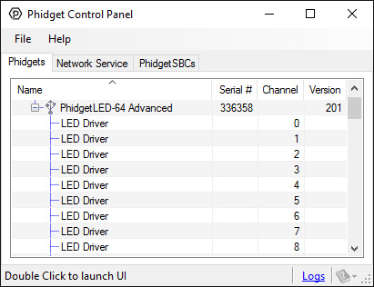
The Phidget Control Panel will list all connected Phidgets and associated objects, as well as the following information:
- Serial number: allows you to differentiate between similar Phidgets.
- Channel: allows you to differentiate between similar objects on a Phidget.
- Version number: corresponds to the firmware version your Phidget is running. If your Phidget is listed in red, your firmware is out of date. Update the firmware by double-clicking the entry.
The Phidget Control Panel can also be used to test your device. Double-clicking on an object will open an example.
Digital Output (LED)
Double-click on a Digital Output object, labelled LED Driver, in order to run the example: [[Image:{{{1}}}_DigitalOutputLED_Example.jpg|center|link=]]
General information about the selected object will be displayed at the top of the window. You can also experiment with the following functionality:
- From the Forward Voltage drop-down menu, select the appropriate voltage for your LED. It is recommended to set the forward voltage to the first setting above the maximum voltage specified by your LED's datasheet.
- Use the Current Limit slider to set an appropriate limit for your LED. The current limit will be specified in your LED's datasheet.
- Use the large button to toggle power to the LED.
- Use the Duty Cycle slider to precisely control the amount of power supplied to the LED.
Testing Using macOS
- Go to the Quick Downloads section on the macOS page.
- Download and run the Phidget macOS Installer
- Click on System Preferences >> Phidgets (under Other) to activate the Preference Pane
- Make sure your device is properly attached
- Double click on your device's objects in the listing to open them. The Preference Pane and examples will function very similarly to the ones described above in the Windows section.
Testing Using Linux
For a general step-by-step guide on getting Phidgets running on Linux, see the Linux page.
Using a Remote OS
We recommend testing your Phidget on a desktop OS before moving on to remote OS. Once you've tested your Phidget, you can go to the PhidgetSBC, or iOS pages to learn how to proceed.
Technical Details
The 1032 uses four controller chips that allow you to vary the current and voltage supplied to each channel. It uses pulse-width modulation to vary the brightness of each LED.
Multiple LEDs on a Single Channel
You can have multiple LEDs hooked up to a single channel on the 1032, (for example, a short string of LEDs) to reduce the amount of wiring, although keep in mind that you'll lose control of the individual lights, and can only toggle or dim the entire string. When using multiple LEDs on a single channel, you'll need to increase the voltage limit for that channel. If the LEDs are too dim at the maximum voltage, you should spread them out to other channels.
High-Current Considerations
If you're using high-current LEDs, you should spread your load evenly across the board to avoid having one of the controller chips overheat. There are four controller chips, each controlling the channels on a quarter of the board.
Controller 1: 0, 1, 2, 3, 4, 5, 6, 7, 24, 25, 26, 27, 28, 29, 30, 31
Controller 2: 8, 9, 10, 11, 12, 13, 14, 15, 16, 17, 18, 19, 20, 21, 22, 23
Controller 3: 32, 33, 34, 35, 36, 37, 38, 39, 56, 57, 58, 59, 60, 61, 62, 63
Controller 4: 40, 41, 42, 43, 44, 45, 46, 47, 48, 49, 50, 51, 52, 53, 54, 55
Board Connector Diagram
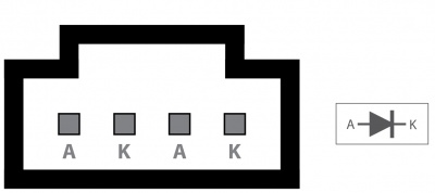
The connector used on the 1032 LED board is a Molex 70543-0003. The mating connector used on our LED cables is the Molex 50-57-9404.
Heat Dissipation and Thermal Protection
Projects that require a high supply voltage, or have a lot of heat being produced from over voltage settings, will have over-temperature problems. This can be mitigated somewhat by understanding how channels are grouped and how the heat is distributed around the controller. On the 1032 channels are split into four groups: (0-7,24-31), (8-23), (32-39, 56-63) and (40-55); each controlled by their own individual IC. Evenly distributing the LEDs that may produce a lot of heat across these groups will balance the load on the ICs and reduce the risk of thermal overload. When thermal overload occurs, the integrated circuit (IC) controlling the involved LEDs will disable the output of all the channels it controls. For example, if an over-temperature occurs due to channel 12, all of the channels 8 through 23 will be disabled by the IC until the temperature back within the operating range. Thermal protection is activated when the die of the IC reaches approximately 160 degrees Celsius. Once the over-temperature fault has been corrected (ie, the IC has cooled down), the output channels will be re-enabled with the same settings as before the thermal shutdown. An error message will be produced during an over-temperature.
Further Reading
For more information, take a look at the LED Primer.
What to do Next
- Programming Languages - Find your preferred programming language here and learn how to write your own code with Phidgets!
- Phidget Programming Basics - Once you have set up Phidgets to work with your programming environment, we recommend you read our page on to learn the fundamentals of programming with Phidgets.
Product History
The 1032 - PhidgetLED-64 replaced our previous LED controller, the 1031 - PhidgetLED-64.