|
|
| Line 1: |
Line 1: |
| <metadesc>A magnetometer works like a digital compass, reporting its orientation relative to the earth's magnetic field. Learn more at Phidgets.com.</metadesc>
| |
| [[Category:Primer]] | | [[Category:Primer]] |
| __TOC__
| | {{TOC limit|2}} |
|
| |
|
| ==Introduction== | | ==Magnetometers and Their Uses== |
| [[File:1042_0.jpg|right|400px|link=]] | | ===Introduction=== |
| A compass is a navigational instrument that is used to determine direction relative to the surface of the earth. Compasses measure direction with respect to the 4 cardinal directions (North, East, South, West) with 0 degrees indicating straight North and 180 degrees indicating straight South.
| | [[File:Magnetometer_Intro.jpg|400px|link=|thumb|Magnetometers Measure Magnetic Field in 3 Axes]] |
| | Compasses are a centuries old technology that have allowed people to quickly get a sense of direction around the globe. As you probably know, they operate on the principle that the earth’s magnetic field points roughly north, no matter where you are (assuming no large sources of interference). To use this time-tested method of navigation with electronics, we recommend incorporating a magnetometer. |
|
| |
|
| Electronic compasses work in exactly the same way as any other compass: They detect the Earth's magnetic field and respond to it. The difference is that an electronic compass uses a magnetometer to detect the field as opposed to a small magnet. This allows them to be much more accurate and allows them to respond more quickly to changes in direction than a traditional compass ever could.
| | Magnetometers measure the strength and direction of magnetic fields, information that when properly applied can feed a compass bearing to your application. Unlike a traditional compass, the readings from Phidgets-based magnetometers operate in all 3 axes, allowing your application to maintain a good sense of direction regardless of orientation. |
|
| |
|
| ==How Compasses Work== | | ===Calibration=== |
| Small compasses found in clocks, mobile phones, and other electronic devices are solid-state compasses, usually built out of two or three magnetic field sensors that provide data for a microprocessor. The correct heading relative to the compass is calculated using trigonometry.
| | In the same way as a physical compass will be thrown off by magnets and metals like steel, your magnetometer will be similarly affected. However, so long as this interference remains consistent, we can adjust the compass calculations to account for these effects in a process called calibration. |
| Often, the device is a discrete component which outputs either a digital or analog signal proportional to its orientation. This signal is interpreted by a controller or microprocessor and used either internally, or sent to a display unit. The sensor uses highly calibrated internal electronics to measure the response of the device to the Earth's magnetic field.
| | [[image:Magnetic_distortion.jpg|link=|thumb|250px|Example of soft iron distortion caused by a large piece of steel.<br>]] |
| | The main thing to consider when calibrating a compass is that any (ferromagnetic) metals near the magnetometer will distort the readings. If the magnetometer is mounted to a moving structure, the structure will shift and bend the magnetic field in unique (but predictable) ways as it rotates. To account for these variations, the compass will need to be calibrated while mounted in the specific location it will be used. Any metal that will move with the compass in practice should move with the compass during calibration, and any metal that will be otherwise near the compass, should be in the same position for calibration. Just know that any stationary sources of magnetic interference (steel girders, etc.) will result in an offset in your heading from earth’s magnetic north. |
|
| |
|
| ===Basic Use===
| | For example, if you are planning to mount a compass in a car, you will need to rotate the whole car with the compass in place when calibrating in order to properly compensate for all the effects of that much moving steel. |
| Compasses are typically used to measure the direction of the object they're mounted on. In order to get the most accurate readings it is recommended to mount the compass to the object in such a way that there is minimal room for shifting around. You will need to calibrate the compass as well.
| |
|
| |
|
| ====Calibration====
| | Basic calibration can only account for distortions in the magnetic field caused by the materials of your structure. Calibration alone will not be able to account for intermittent or variable effects, such as electric motors turning on nearby, or large pieces of steel moving independently of your application. To minimize these effects, be sure to keep your magnetometer as far away from sources of magnetic interference as possible. |
| Calibration involves setting the compass up to handle the magnetic field characteristics in your particular region of the world as well as interference caused by a more localized magnetic fields such as speaker magnets. To calibrate effectively you will need to determine the Earth's magnetic field strength at your location. This data is available on line in the form of [http://www.ngdc.noaa.gov/geomag-web/#igrfwmm magnetic field calculators]; all you have to do is enter in your zip or postal code.
| |
|
| |
|
| Calibration is ''required'' for any applications needing more accuracy than being able to discern a simple North, East, South, or West direction. If you have already gathered compass data, you can retroactively calibrate that data by applying the same calibration formula to each data point.
| | Unfortunately, if you are in a magnetically varied environment, or if your environment changes after calibration, you will not be able to fully rely on your compass for an accurate heading. These scenarios could be as simple as driving your car across a big steel bridge, or as contrived as loading an airplane full of magnets. Thankfully, most places are far enough away from such interference, and the magnetic compass maintains its usefulness. |
|
| |
|
| | <div class="phd-deck-sequence"> |
| | __NOTOC__ |
| | {{PTX_COMPASSCAL}} |
| | </div> |
|
| |
|
| For more information about calibration, check the [[:Category:UserGuide|user guide]] for your Phidget. | | ===Calculating Heading=== |
| | For most applications, we recommend using the [[Spatial_Primer|Spatial]] object to get a direct readout of compass heading, as it has already been processed and combined with accelerometer and gyroscope data for the most consistent results. |
|
| |
|
| ==Interference==
| | Note that if you want to account for “true north” as your heading, you will need to account for the declination of the earth’s magnetic field at your location. The earth’s magnetic north pole and the north pole on a map are not the same, and this will need to be accounted for. The exact process of finding your declination is outside of the scope of this document. |
| The most common problem compass users can expect to face is interference. Interference will generally cause the compass to behave poorly. Usually this means inconsistent, fluctuating, or inaccurate readings. Luckily most forms of interference are fairly easy to deal with.
| |
|
| |
|
| ===What are likely sources of interference and how are they handled?===
| | It is important to note here, that nearby sources of interference outside of the moving structure could skew readings away from the declination angle, and additional compensation may be required. |
| [[image:nodistortion.gif|thumb|400px|link=|Approximation of 2 axis magnetic field data with 0 distortion.<br>[[Media:nodistortion.gif|Full-Sized Image]]]]
| |
| There are 4 main categories of interference. Some are easy to get rid of via calibration, others are not easy or even impossible to get rid of.
| |
|
| |
|
| If you rotate the compass through a full 360 degrees and plot the resulting data on an x-y plane you will get a circle centered at the origin. This can be extended to a 3 axis compass which would generate a sphere. However, certain characteristics of the environment can have a distorting effect on this magnetic data. In fact, the magnitude of the distortion is regularly many times the that of the actual signal.
| | While the actual calculations are also outside the scope of this document, if you still want to calculate heading on your own, you will also need to be aware of the fact that the earth’s magnetic field is not parallel to the surface at most latitudes. This means that unless your compass is perfectly flat, you will need to account for sensor’s tilt relative to the earth’s surface for an accurate reading of heading. The heading output from your [[Spatial_Primer|Phidget Spatial]] object is already compensated for such effects. |
| <br clear = "all">
| |
|
| |
|
| ===="Hard Iron" Interference==== | | ==Demonstrations Using the Control Panel Example== |
| [[image:harddistortion.gif|thumb|link=|400px|Approximation of magnetic field with hard iron distortion.<br>[[Media:harddistortion.gif|Full-Sized Image]]]] | | [[File:Magnetometer_Example.jpg|400px|link=|thumb|The Phidgets Control Panel Magnetometer Example]] |
| So called ''hard iron'' interference is caused by static magnetic fields associated with the enviornment. For example, this could include any minor (or major) magnetism in the metal chassis or frame of a vehicle, any actual magnets such as speakers, etc... This interference pattern is unique to the environment but is constant. If you have your compass in an enclosure that is held together with metal screws even these relatively small amounts of ferromagnetic material can cause issues. If we consider the magnetic data circle, hard iron interference has the effect of x/y(/z in the case of 3 axes) shifting the entire circle away from the origin by some amount. The amount is dependent on any number of different factors and can be very large. The important part is that this shift is the same for all points in time so it can be calibrated out very easily with a numeric offset which is taken care of by the calibration process.
| |
| <br clear = "all">
| |
|
| |
|
| ===="Soft Iron" Interference====
| | The magnetometer example displays the direction magnitude of the measured magnetic field in the X and Y axes as a line from the center of a circle. The red or green circle shows the strength of the magnetic field traveling through the top of the sensor. The larger the circle, the greater the effect. Red indicates a field pointing into the top of the sensor, green indicates a field pointing up from the bottom. |
| [[image:softdistortion.gif|link=|right|thumb|350px|Approximation of magnetic field with soft iron distortion.<br>[[Media:softdistortion.gif|Full-Sized Image]]]]
| |
| ''Soft iron'' interference is caused by distortion of the Earth's magnetic field due to materials in the environment. Think of it like electricity - the magnetic field is looking for the easiest path to get to where it is going. Since magnetic fields can flow more easily through ferromagnetic materials than air, more of the field will flow through the ferromagnetic material than you would expect if it were just air. This distortion effect causes the magnetic field lines to be bent sometimes quite a bit. Note that unlike hard iron interference which is the result of materials which actually have a magnetic field of their own, soft iron interference is caused by non-magnetic materials distorting the Earth's magnetic field. This type of interference has a squishing effect on the magnetic data circle turning it into more of an ellipsoid shape. The distortion in this case depends on the direction that the compass is facing. Because of this, the distortion cannot be calibrated out with a simple offset, more complicated math will still let the compass account for this type of interference though.
| |
| <br clear = "all">
| |
| [[image:Magnetic_distortion.jpg|link=|thumb|center|250px|Example of soft iron distortion caused by an ''external'' object.<br>]]
| |
|
| |
|
| ====Dynamic magnetic fields associated with application====
| | Similarly, the X and Y components of the field are indicated by a line in the center of the circle. Out of the box, you may notice that when your compass is placed flat on a table, and rotated in a circle, the magnetic field indicator in X and Y doesn’t actually follow a circle of even magnitude. This is an indication you will need to calibrate your compass. Calibrate it now, and come back. You can begin calibration by clicking the “Calibrate” button. |
| If you are using a compass in a robot or vehicle, there is likely many more devices running at the same time. The wiring associated with these devices will create its own, dynamic magnetic field. Particularly bad offenders are electric motors that are running. The magnetic fields of these devices are constantly changing and calibration will only provide small (if any) benefits. The best thing that can be done to avoid this sort of interference is to mount the compass as far away from other electronics as possible.
| |
|
| |
|
| ====Static or Dynamic fields not associated with application====
| | If your compass is properly calibrated, by placing it flat on a table you should notice the length of the line remains about the same while the magnetometer is rotated. If it’s still not behaving this way, first try moving your sensor to the side a distance, and see how that effects your results. If the sensor reading moves, this indicates it is probably close to something steel, or magnetic, such as screws in the table. Otherwise, try calibrating again and check your results. |
| These are the most difficult to handle. A very common cause of this sort of interference is steel or iron re-bar in concrete floors. Steel studs in office or commercial buildings are also a problem. In general any environmental (i.e. external) sources of hard or soft iron distortion can cause issues (especially if the compass is in a vehicle, which is moving around). There is no practical way to account for this. The best thing you can do is to take a simple handheld compass and move it around in the area you intend the electronic compass to be operating. Does the compass report reasonable directions? If so then your system will likely function well. If not, the area is simply too noisy to use an electronic compass.
| |
|
| |
|
| ====Combinations====
| | The next thing you may notice is that the line is relatively short, and there is a larger than expected field going through the device vertically. (i.e. the red/green circle is large). In most places on the face of the earth, the magnetic field isn’t directly parallel to the surface, and may in fact be pointing into, or outwards from the surface. As you tilt the sensor away from the table, you may notice the effects of rotating your sensor are strongly skewed when used in any orientation that isn’t flat. |
| In practical applications most of these types of interference work in combination. Because of all of this, to use a compass calibration is required. | | |
| | In fact, you should be able to orient your sensor such that the line in the middle of the diagram becomes a dot, while the outer circle is at its largest. If you were to draw a line out from the face of your sensor, this is the actual tilt of the magnetic field at your location. At the location of the Phidgets offices, we find that the earth’s magnetic field is pointed mostly at the ground, rather than alongside it. |
|
| |
|
| ==Declination==
| | If you were making heading calculations on your own, you would need to account for this effect in any scenario where you can’t guarantee your sensor will remain flat. |
| Over long periods of time, changes in the Earth's magnetic core have an effect on the Earth's magnetic field. What this means is that the North magnetic pole shifts and is not the same as ''true'' North. The time it takes for magnetic North to shift significantly is very long so for all intents and purposes the magnetic North pole is stationary, it is just important to note that it is not in the same place as the actual North pole. Since compasses measure direction as a function of magnetic field strength, the direction a compass tells you is North is in fact magnetic North. As you might imagine the amount that magnetic North and true North differ is a function of your location. It is technically possible for your compass to point in the exact opposite direction from North if you are directly between the North pole and the magnetic North pole. The most common way to get declination is from a map that has isogonic lines. Isogonic lines are lines of equal declination similar to contour lines on topographic maps that show elevation. The lines will give a reasonable approximation of the declination for your region. For example, take a look at the map below and try to determine what the declination is in your city:
| |
| [[File: declination_small.jpg|link={{SERVER}}/docs/images/f/f3/Declination.jpg]]
| |
|
| |
|
| | | By using a [[Spatial_Primer|Phidget Spatial]] you can get a readout of the compass bearing directly, that accounts for the tilt of the sensor, using the ''heading'' component of the Euler angles provided. |
| For the purposes of calculation assume that East declination is positive and West is negative. This means that you need to subtract the declination from your heading when your declination is to the East and vice versa when it is West.
| |
| | |
| ==Noise==
| |
| As with all electronics, electronic compasses will be effected by some amount of noise, usually caused by thermal and mechanical fluctuations inside the sensor. Noise levels will be different for each axis, because each orientation of sensor is build slightly differently (for example, it is much more difficult to get low noise from the vertical axis because the sensor is a flat piece of silicon. Two of the major types of noise are white noise and random walk.
| |
| | |
| ===White Noise===
| |
| White noise is the short-term noise that is contributed to from a number of internal and external factors. For example, when a compass is stationary on your desk, it might read 100μG one sample, 101μG another sample, and 97μG in yet another sample. Luckily, white noise is usually fairly consistent which means it can be mitigated quite effectively if you average multiple samples together. With a Phidgets compass, if you select a data rate slower than its maximum it will automatically average as many samples as it can within that time frame for each value. In applications where you need an extremely fast sampling rate, and can't afford to spend time averaging samples, you should look for a compass with low white noise. Also keep in mind the noisiness of your environment- For example, the engine and road noise on a bus will easily be more noisy than the compass - so there is no point in paying for a low noise device. See the [[Allan Deviation Primer]] for more information on spatial noise characteristics.
| |
| | |
| | |
| ===Random Walk===
| |
| Often called drift, random walk is the long-term noise that causes samples to gradually become further and further away from their true values. This type of noise is less important for applications with constant movement and a fast sampling rate, but for applications where values are averaged over longer periods of time, it can cause severe inaccuracies. See the [[Allan Deviation Primer]] for more information on noise characteristics.
| |
| | |
| ==Calculating Heading from Magnetometer Data==
| |
| The three axis magnetometer data can be used, along with pitch and roll angles calculated from the accelerometer, to find a magnetic bearing, just like a physical compass. In order for the compass to be accurate at all, calibration must have been done to factor out hard and soft iron offsets.
| |
| | |
| The magnetic field is represented as a vector. If the Phidget is completely level with respect to gravity, then we can calculate magnetic bearing easily by looking at the x and y components of the vector, which simply represents an angle between 0 and 360 degrees on the unit circle.
| |
| | |
| However, when the board is not level, the magnetic field vector components in each axis will be skewed, or is other words, what we need to know is the magnetic field with respect to the earth frame, and what we have is the magnetic field with respect to the Phidget, which is rotated with respect to the earth. What needs to be done is to rotate the magnetic field vector back into the earth frame, we can then use the x-y components to again determine bearing. The easiest way to do this is to find the board pitch and roll angles using the accelerometer, and then build a rotation matrix using these angles to rotate the magnetic field vector into the earth frame (ie aligned with gravity). For example, here is an excerpt from our C# example code which shows how this is done:
| |
| | |
| | |
| <syntaxhighlight lang=csharp>
| |
| //This finds a magnetic north bearing, correcting for board tilt and roll as measured by the accelerometer
| |
| //This doesn't account for dynamic acceleration - ie accelerations other than gravity will throw off the calculation
| |
| //Calculations based on AN4248
| |
| double[] lastAngles = { 0, 0, 0 };
| |
| void calculateCompassBearing(SpatialSpatialDataEventArgs e) {
| |
| double[] gravity = {
| |
| e.Acceleration[0],
| |
| e.Acceleration[1],
| |
| e.Acceleration[2]};
| |
| | |
| double[] magField = {
| |
| e.MagneticField[0],
| |
| e.MagneticField[1],
| |
| e.MagneticField[2]};
| |
| | |
| //Roll Angle - about axis 0
| |
| // tan(roll angle) = gy/gz
| |
| // Use Atan2 so we have an output os (-180 - 180) degrees
| |
| double rollAngle = Math.Atan2(gravity[1], gravity[2]);
| |
| | |
| //Pitch Angle - about axis 1
| |
| // tan(pitch angle) = -gx / (gy * sin(roll angle) * gz * cos(roll angle))
| |
| // Pitch angle range is (-90 - 90) degrees
| |
| double pitchAngle = Math.Atan(-gravity[0] / (gravity[1] * Math.Sin(rollAngle) + gravity[2] * Math.Cos(rollAngle)));
| |
| | |
| //Yaw Angle - about axis 2
| |
| // tan(yaw angle) = (mz * sin(roll) – my * cos(roll)) /
| |
| // (mx * cos(pitch) + my * sin(pitch) * sin(roll) + mz * sin(pitch) * cos(roll))
| |
| // Use Atan2 to get our range in (-180 - 180)
| |
| //
| |
| // Yaw angle == 0 degrees when axis 0 is pointing at magnetic north
| |
| double yawAngle = Math.Atan2(magField[2] * Math.Sin(rollAngle) - magField[1] * Math.Cos(rollAngle),
| |
| magField[0] * Math.Cos(pitchAngle) + magField[1] * Math.Sin(pitchAngle) * Math.Sin(rollAngle) + magField[2] * Math.Sin(pitchAngle) * Math.Cos(rollAngle));
| |
| | |
| double[] angles = { rollAngle, pitchAngle, yawAngle };
| |
| | |
| //we low-pass filter the angle data so that it looks nicer on-screen
| |
| try {
| |
| //make sure the filter buffer doesn't have values passing the -180<->180 mark
| |
| //Only for Roll and Yaw - Pitch will never have a sudden switch like that
| |
| for (int i = 0; i < 3; i += 2) {
| |
| if (Math.Abs(angles[i] - lastAngles[i]) > 3)
| |
| foreach (double[] value in compassBearingFilter)
| |
| if (angles[i] > lastAngles[i])
| |
| value[i] += 360 * Math.PI / 180.0;
| |
| else
| |
| value[i] -= 360 * Math.PI / 180.0;
| |
| }
| |
| | |
| lastAngles = (double[])angles.Clone();
| |
| | |
| compassBearingFilter.Add((double[])angles.Clone());
| |
| if (compassBearingFilter.Count > compassBearingFilterSize)
| |
| compassBearingFilter.RemoveAt(0);
| |
| | |
| yawAngle = pitchAngle = rollAngle = 0;
| |
| foreach (double[] stuff in compassBearingFilter) {
| |
| rollAngle += stuff[0];
| |
| pitchAngle += stuff[1];
| |
| yawAngle += stuff[2];
| |
| }
| |
| yawAngle /= compassBearingFilter.Count;
| |
| pitchAngle /= compassBearingFilter.Count;
| |
| rollAngle /= compassBearingFilter.Count;
| |
| | |
| //Convert radians to degrees for display
| |
| compassBearing = yawAngle * (180.0 / Math.PI);
| |
| | |
| bearingTxt.Text = compassBearing.ToString("F1") + "°";
| |
| pitchAngleTxt.Text = (pitchAngle * (180.0 / Math.PI)).ToString("F1") + "°";
| |
| rollAngleTxt.Text = (rollAngle * (180.0 / Math.PI)).ToString("F1") + "°";
| |
| } catch { }
| |
| }
| |
| </syntaxhighlight>
| |
Magnetometers and Their Uses
Introduction
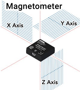
Magnetometers Measure Magnetic Field in 3 Axes
Compasses are a centuries old technology that have allowed people to quickly get a sense of direction around the globe. As you probably know, they operate on the principle that the earth’s magnetic field points roughly north, no matter where you are (assuming no large sources of interference). To use this time-tested method of navigation with electronics, we recommend incorporating a magnetometer.
Magnetometers measure the strength and direction of magnetic fields, information that when properly applied can feed a compass bearing to your application. Unlike a traditional compass, the readings from Phidgets-based magnetometers operate in all 3 axes, allowing your application to maintain a good sense of direction regardless of orientation.
Calibration
In the same way as a physical compass will be thrown off by magnets and metals like steel, your magnetometer will be similarly affected. However, so long as this interference remains consistent, we can adjust the compass calculations to account for these effects in a process called calibration.
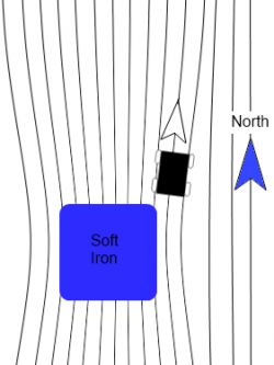
Example of soft iron distortion caused by a large piece of steel.
The main thing to consider when calibrating a compass is that any (ferromagnetic) metals near the magnetometer will distort the readings. If the magnetometer is mounted to a moving structure, the structure will shift and bend the magnetic field in unique (but predictable) ways as it rotates. To account for these variations, the compass will need to be calibrated while mounted in the specific location it will be used. Any metal that will move with the compass in practice should move with the compass during calibration, and any metal that will be otherwise near the compass, should be in the same position for calibration. Just know that any stationary sources of magnetic interference (steel girders, etc.) will result in an offset in your heading from earth’s magnetic north.
For example, if you are planning to mount a compass in a car, you will need to rotate the whole car with the compass in place when calibrating in order to properly compensate for all the effects of that much moving steel.
Basic calibration can only account for distortions in the magnetic field caused by the materials of your structure. Calibration alone will not be able to account for intermittent or variable effects, such as electric motors turning on nearby, or large pieces of steel moving independently of your application. To minimize these effects, be sure to keep your magnetometer as far away from sources of magnetic interference as possible.
Unfortunately, if you are in a magnetically varied environment, or if your environment changes after calibration, you will not be able to fully rely on your compass for an accurate heading. These scenarios could be as simple as driving your car across a big steel bridge, or as contrived as loading an airplane full of magnets. Thankfully, most places are far enough away from such interference, and the magnetic compass maintains its usefulness.
Magnetometer Calibration Guide
In order for your magnetometer to provide accurate heading information, it must be calibrated.
Follow this guide to complete the calibration process.
1. Open the Magnetometer example for your device, and click the Calibrate button. This will open the Compass Calibration tool.
2. If your device supports heating, we recommend checking the HeatingEnabled checkbox. Wait for the temperature reading to turn green:
If your Spatial does not support heating (neither of the above controls will be available), you can skip this step.
3. Next, decide if you're using 2-axis or 3-axis calibration:
● If the spatial is free to move in all directions, use 3-axis
● If the spatial is being kept mostly level (e.g. in a car), use 2-axis
4. You can leave the Local Field Strength at 1.0 for general use since magnitude doesn't affect heading. If you need more quantitative results, look up
your local value.
5. Make sure your Phidget Spatial is firmly in the position you intend to calibrate it for, and begin by clicking the Start button.
Begin rotating the structure your Phidget is mounted to. Notice the red dots appearing on the graph.
6. Try to rotate it so that it fills out as much of the sphere (or circle in 2-axis mode) as possible. When you're finished, click Stop.
You should now see red and green spheres (or circles) in the graph. The red one is the raw measurements, and the green one is the calibrated measurements.
Newly calibrated data from the magnetometer will be indicated by a green line that matches the sphere. The green sphere should be more centered than the red
one. If not, try repeating the calibration.
You're now done the calibration process! On most Phidget Spatials, the calibration will be stored in flash, so it stays calibrated to this environment even
across power cycles.
7. If you need to repeat this exact calibration, you can save the values listed in the text box.
You can use these values in the setMagnetometerCorrectionParameters method. See our
API Documentation for more details.
Calculating Heading
For most applications, we recommend using the Spatial object to get a direct readout of compass heading, as it has already been processed and combined with accelerometer and gyroscope data for the most consistent results.
Note that if you want to account for “true north” as your heading, you will need to account for the declination of the earth’s magnetic field at your location. The earth’s magnetic north pole and the north pole on a map are not the same, and this will need to be accounted for. The exact process of finding your declination is outside of the scope of this document.
It is important to note here, that nearby sources of interference outside of the moving structure could skew readings away from the declination angle, and additional compensation may be required.
While the actual calculations are also outside the scope of this document, if you still want to calculate heading on your own, you will also need to be aware of the fact that the earth’s magnetic field is not parallel to the surface at most latitudes. This means that unless your compass is perfectly flat, you will need to account for sensor’s tilt relative to the earth’s surface for an accurate reading of heading. The heading output from your Phidget Spatial object is already compensated for such effects.
Demonstrations Using the Control Panel Example
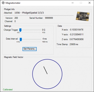
The Phidgets Control Panel Magnetometer Example
The magnetometer example displays the direction magnitude of the measured magnetic field in the X and Y axes as a line from the center of a circle. The red or green circle shows the strength of the magnetic field traveling through the top of the sensor. The larger the circle, the greater the effect. Red indicates a field pointing into the top of the sensor, green indicates a field pointing up from the bottom.
Similarly, the X and Y components of the field are indicated by a line in the center of the circle. Out of the box, you may notice that when your compass is placed flat on a table, and rotated in a circle, the magnetic field indicator in X and Y doesn’t actually follow a circle of even magnitude. This is an indication you will need to calibrate your compass. Calibrate it now, and come back. You can begin calibration by clicking the “Calibrate” button.
If your compass is properly calibrated, by placing it flat on a table you should notice the length of the line remains about the same while the magnetometer is rotated. If it’s still not behaving this way, first try moving your sensor to the side a distance, and see how that effects your results. If the sensor reading moves, this indicates it is probably close to something steel, or magnetic, such as screws in the table. Otherwise, try calibrating again and check your results.
The next thing you may notice is that the line is relatively short, and there is a larger than expected field going through the device vertically. (i.e. the red/green circle is large). In most places on the face of the earth, the magnetic field isn’t directly parallel to the surface, and may in fact be pointing into, or outwards from the surface. As you tilt the sensor away from the table, you may notice the effects of rotating your sensor are strongly skewed when used in any orientation that isn’t flat.
In fact, you should be able to orient your sensor such that the line in the middle of the diagram becomes a dot, while the outer circle is at its largest. If you were to draw a line out from the face of your sensor, this is the actual tilt of the magnetic field at your location. At the location of the Phidgets offices, we find that the earth’s magnetic field is pointed mostly at the ground, rather than alongside it.
If you were making heading calculations on your own, you would need to account for this effect in any scenario where you can’t guarantee your sensor will remain flat.
By using a Phidget Spatial you can get a readout of the compass bearing directly, that accounts for the tilt of the sensor, using the heading component of the Euler angles provided.