REL2103 User Guide: Difference between revisions
(→About) |
|||
| (4 intermediate revisions by the same user not shown) | |||
| Line 4: | Line 4: | ||
[[Category:UserGuide]] | [[Category:UserGuide]] | ||
==Part 1: Setup== | ==Part 1: Setup== | ||
{{ | {{PT1 Deck Sequence}} | ||
==Part 2: Using Your Phidget== | ==Part 2: Using Your Phidget== | ||
===About=== | ===About=== | ||
The REL2103 is a solid-state relay capable of switching up to 10 amps or controlling power up to 30V. You interact with the REL2103 through the Digital Output Channel Class to turn on or off the power to a circuit. | The REL2103 is a solid-state relay capable of switching up to 10 amps or controlling power up to 30V. You interact with the REL2103 through the Digital Output Channel Class to turn on or off the power to a circuit. | ||
[[Image:REL2103_About.jpg|link=|center]] | |||
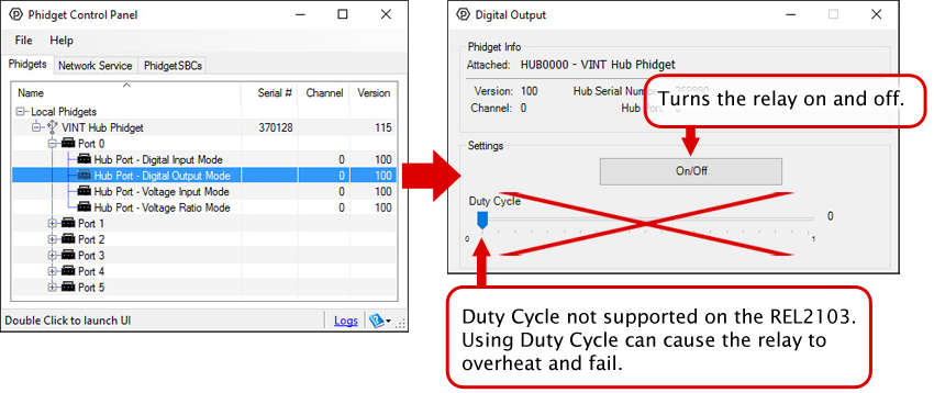
===Explore your Phidget Channels Using the Control Panel=== | ===Explore your Phidget Channels Using the Control Panel=== | ||
Double click on the Digital Output channel class under the port your REL2103 is connected to. | Double click on the Digital Output channel class under the port your REL2103 is connected to. | ||
[[Image:REL2103_0_Panel_Example.jpg | [[Image:REL2103_0_Panel_Example.jpg|link=]] | ||
{{UG-Part3}} | {{UG-Part3}} | ||
| Line 39: | Line 24: | ||
{{UGC-Entry|Solid State Relays| | {{UGC-Entry|Solid State Relays| | ||
| | | | ||
A solid-state relay is an electrically-controlled switch. For more information about how SSRs work and how to use them, visit the [[Solid State Relay | A solid-state relay is an electrically-controlled switch. For more information about how SSRs work and how to use them, visit the [[Solid State Relay Guide]].}} | ||
{{UGC-Entry|Using the SRC Terminals| | {{UGC-Entry|Using the SRC Terminals| | ||
| | | | ||
| Line 48: | Line 33: | ||
The white schematic on the left shows a simplified version of the REL2103's circuitry: An optocoupler that activates two MOSFETs. The black schematic on the right shows how you would hook up a DC circuit to take advantage of the increased maximum current.}} | The white schematic on the left shows a simplified version of the REL2103's circuitry: An optocoupler that activates two MOSFETs. The black schematic on the right shows how you would hook up a DC circuit to take advantage of the increased maximum current.}} | ||
{{UGC-Entry|Can I use this relay without a VINT Hub?| | |||
| | |||
Unlike most VINT devices that communicate to the VINT Hub by sending packets on the data line, the REL2103 is simply controlled with the port in digital output mode. This means that you can control it with other digital output devices. For example, you can control it with a Phidget 1018 like this: | |||
[[Image:REL2XXX_1018.png|link=|500px]] | |||
Here's a simplified diagram to clarify how the input side of REL2103 works: | |||
[[Image:REL2103_circuit.png|link=|650px]] | |||
The red wire requires 5V to power the opto-isolator diode, and the white wire requires at least 3.3V to switch the MOSFET. | |||
}} | |||
{{UGC-End}} | {{UGC-End}} | ||
Latest revision as of 19:15, 8 May 2026
Part 1: Setup
Part 2: Using Your Phidget
About
The REL2103 is a solid-state relay capable of switching up to 10 amps or controlling power up to 30V. You interact with the REL2103 through the Digital Output Channel Class to turn on or off the power to a circuit.

Explore your Phidget Channels Using the Control Panel
Double click on the Digital Output channel class under the port your REL2103 is connected to.
Part 3: Create your Program
Part 4: Advanced Topics and Troubleshooting
Before you open a Phidget channel in your program, you can set these properties to specify which channel to open. You can find this information through the Control Panel.
1. Open the Control Panel and double-click on the red map pin icon:

2. The Addressing Information window will open. Here you will find all the information you need to address your Phidget in your program.

See the Phidget22 API for your language to determine exact syntax for each property.
A solid-state relay is an electrically-controlled switch. For more information about how SSRs work and how to use them, visit the Solid State Relay Guide.
The two middle pins on the REL2103, labeled "SRC" give you access to the source of the MOSFETs used to switch your circuit. If you are switching a DC load, the setup will be advantageous as you can double the maximum current handled by this Phidget (10A to 20A).

The white schematic on the left shows a simplified version of the REL2103's circuitry: An optocoupler that activates two MOSFETs. The black schematic on the right shows how you would hook up a DC circuit to take advantage of the increased maximum current.
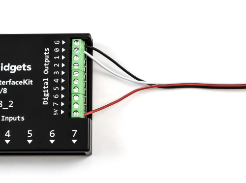
Unlike most VINT devices that communicate to the VINT Hub by sending packets on the data line, the REL2103 is simply controlled with the port in digital output mode. This means that you can control it with other digital output devices. For example, you can control it with a Phidget 1018 like this:
Here's a simplified diagram to clarify how the input side of REL2103 works:
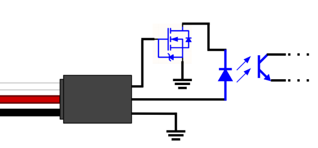
The red wire requires 5V to power the opto-isolator diode, and the white wire requires at least 3.3V to switch the MOSFET.