Magnetometer Guide: Difference between revisions
No edit summary |
|||
| (40 intermediate revisions by 5 users not shown) | |||
| Line 1: | Line 1: | ||
[[Category: | {{#seo:|description=How do you use the data from a magnetometer or compass? Learn how to calibrate the magnetometer and calculate a heading from the axis data.}} | ||
{{#seo:|keywords=magnetometer}} | |||
[[Category:IntroGuide]] | |||
{{TOC limit|3}} | |||
==Introduction== | ==Magnetometers and Their Uses== | ||
===Introduction=== | |||
[[File:Magnetometer_Intro.jpg|400px|link=|thumb|Magnetometers Measure Magnetic Field in 3 Axes]] | |||
Compasses are a centuries old technology that have allowed people to quickly get a sense of direction around the globe. As you probably know, they operate on the principle that the earth’s magnetic field points roughly north, no matter where you are (assuming no large sources of interference). To use this time-tested method of navigation with electronics, we recommend incorporating a magnetometer. | |||
Magnetometers measure the strength and direction of magnetic fields, information that when properly applied can feed a compass bearing to your application. Unlike a traditional compass, the readings from Phidgets-based magnetometers operate in all 3 axes, allowing your application to maintain a good sense of direction regardless of orientation. | |||
== | ===Calibration=== | ||
In the same way as a physical compass will be thrown off by magnets and metals like steel, your magnetometer will be similarly affected. However, so long as this interference remains consistent, we can adjust the compass calculations to account for these effects in a process called calibration. | |||
[[image:Magnetic_distortion.jpg|link=|thumb|250px|Example of soft iron distortion caused by a large piece of steel.<br>]] | |||
The main thing to consider when calibrating a compass is that any (ferromagnetic) metals near the magnetometer will distort the readings. If the magnetometer is mounted to a moving structure, the structure will shift and bend the magnetic field in unique (but predictable) ways as it rotates. To account for these variations, the compass will need to be calibrated while mounted in the specific location it will be used. Any metal that will move with the compass in practice should move with the compass during calibration, and any metal that will be otherwise near the compass, should be in the same position for calibration. Just know that any stationary sources of magnetic interference (steel girders, etc.) will result in an offset in your heading from earth’s magnetic north. | |||
For example, if you are planning to mount a compass in a car, you will need to rotate the whole car with the compass in place when calibrating in order to properly compensate for all the effects of that much moving steel. | |||
Basic calibration can only account for distortions in the magnetic field caused by the materials of your structure. Calibration alone will not be able to account for intermittent or variable effects, such as electric motors turning on nearby, or large pieces of steel moving independently of your application. To minimize these effects, be sure to keep your magnetometer as far away from sources of magnetic interference as possible. | |||
Unfortunately, if you are in a magnetically varied environment, or if your environment changes after calibration, you will not be able to fully rely on your compass for an accurate heading. These scenarios could be as simple as driving your car across a big steel bridge, or as contrived as loading an airplane full of magnets. Thankfully, most places are far enough away from such interference, and the magnetic compass maintains its usefulness. | |||
<div class="phd-deck-sequence"> | |||
__NOTOC__ | |||
{{PTX_COMPASSCAL}} | |||
</div> | |||
== | ===Calculating Heading=== | ||
For most applications, we recommend using the [[Spatial_Primer|Spatial]] object to get a direct readout of compass heading, as it has already been processed and combined with accelerometer and gyroscope data for the most consistent results. | |||
Note that if you want to account for “true north” as your heading, you will need to account for the declination of the earth’s magnetic field at your location. The earth’s magnetic north pole and the north pole on a map are not the same, and this will need to be accounted for. The exact process of finding your declination is outside of the scope of this document. | |||
It is important to note here, that nearby sources of interference outside of the moving structure could skew readings away from the declination angle, and additional compensation may be required. | |||
While the actual calculations are also outside the scope of this document, if you still want to calculate heading on your own, you will also need to be aware of the fact that the earth’s magnetic field is not parallel to the surface at most latitudes. This means that unless your compass is perfectly flat, you will need to account for sensor’s tilt relative to the earth’s surface for an accurate reading of heading. The heading output from your [[Spatial_Primer|Phidget Spatial]] object is already compensated for such effects. | |||
==Demonstrations Using the Control Panel Example== | |||
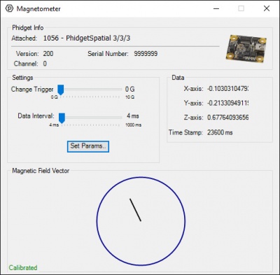
[[File:Magnetometer_Example.jpg|400px|link=|thumb|The Phidgets Control Panel Magnetometer Example]] | |||
The magnetometer example displays the direction magnitude of the measured magnetic field in the X and Y axes as a line from the center of a circle. The red or green circle shows the strength of the magnetic field traveling through the top of the sensor. The larger the circle, the greater the effect. Red indicates a field pointing into the top of the sensor, green indicates a field pointing up from the bottom. | |||
Similarly, the X and Y components of the field are indicated by a line in the center of the circle. Out of the box, you may notice that when your compass is placed flat on a table, and rotated in a circle, the magnetic field indicator in X and Y doesn’t actually follow a circle of even magnitude. This is an indication you will need to calibrate your compass. Calibrate it now, and come back. You can begin calibration by clicking the “Calibrate” button. | |||
If your compass is properly calibrated, by placing it flat on a table you should notice the length of the line remains about the same while the magnetometer is rotated. If it’s still not behaving this way, first try moving your sensor to the side a distance, and see how that effects your results. If the sensor reading moves, this indicates it is probably close to something steel, or magnetic, such as screws in the table. Otherwise, try calibrating again and check your results. | |||
The next thing you may notice is that the line is relatively short, and there is a larger than expected field going through the device vertically. (i.e. the red/green circle is large). In most places on the face of the earth, the magnetic field isn’t directly parallel to the surface, and may in fact be pointing into, or outwards from the surface. As you tilt the sensor away from the table, you may notice the effects of rotating your sensor are strongly skewed when used in any orientation that isn’t flat. | |||
In fact, you should be able to orient your sensor such that the line in the middle of the diagram becomes a dot, while the outer circle is at its largest. If you were to draw a line out from the face of your sensor, this is the actual tilt of the magnetic field at your location. At the location of the Phidgets offices, we find that the earth’s magnetic field is pointed mostly at the ground, rather than alongside it. | |||
If you were making heading calculations on your own, you would need to account for this effect in any scenario where you can’t guarantee your sensor will remain flat. | |||
[[ | By using a [[Spatial_Primer|Phidget Spatial]] you can get a readout of the compass bearing directly, that accounts for the tilt of the sensor, using the ''heading'' component of the Euler angles provided. | ||
Latest revision as of 20:23, 13 July 2023
Magnetometers and Their Uses
Introduction
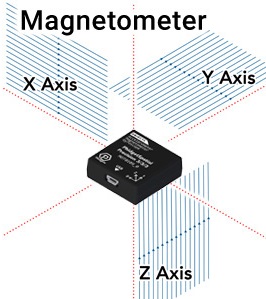
Compasses are a centuries old technology that have allowed people to quickly get a sense of direction around the globe. As you probably know, they operate on the principle that the earth’s magnetic field points roughly north, no matter where you are (assuming no large sources of interference). To use this time-tested method of navigation with electronics, we recommend incorporating a magnetometer.
Magnetometers measure the strength and direction of magnetic fields, information that when properly applied can feed a compass bearing to your application. Unlike a traditional compass, the readings from Phidgets-based magnetometers operate in all 3 axes, allowing your application to maintain a good sense of direction regardless of orientation.
Calibration
In the same way as a physical compass will be thrown off by magnets and metals like steel, your magnetometer will be similarly affected. However, so long as this interference remains consistent, we can adjust the compass calculations to account for these effects in a process called calibration.
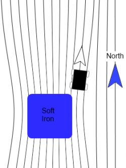
The main thing to consider when calibrating a compass is that any (ferromagnetic) metals near the magnetometer will distort the readings. If the magnetometer is mounted to a moving structure, the structure will shift and bend the magnetic field in unique (but predictable) ways as it rotates. To account for these variations, the compass will need to be calibrated while mounted in the specific location it will be used. Any metal that will move with the compass in practice should move with the compass during calibration, and any metal that will be otherwise near the compass, should be in the same position for calibration. Just know that any stationary sources of magnetic interference (steel girders, etc.) will result in an offset in your heading from earth’s magnetic north.
For example, if you are planning to mount a compass in a car, you will need to rotate the whole car with the compass in place when calibrating in order to properly compensate for all the effects of that much moving steel.
Basic calibration can only account for distortions in the magnetic field caused by the materials of your structure. Calibration alone will not be able to account for intermittent or variable effects, such as electric motors turning on nearby, or large pieces of steel moving independently of your application. To minimize these effects, be sure to keep your magnetometer as far away from sources of magnetic interference as possible.
Unfortunately, if you are in a magnetically varied environment, or if your environment changes after calibration, you will not be able to fully rely on your compass for an accurate heading. These scenarios could be as simple as driving your car across a big steel bridge, or as contrived as loading an airplane full of magnets. Thankfully, most places are far enough away from such interference, and the magnetic compass maintains its usefulness.
Calculating Heading
For most applications, we recommend using the Spatial object to get a direct readout of compass heading, as it has already been processed and combined with accelerometer and gyroscope data for the most consistent results.
Note that if you want to account for “true north” as your heading, you will need to account for the declination of the earth’s magnetic field at your location. The earth’s magnetic north pole and the north pole on a map are not the same, and this will need to be accounted for. The exact process of finding your declination is outside of the scope of this document.
It is important to note here, that nearby sources of interference outside of the moving structure could skew readings away from the declination angle, and additional compensation may be required.
While the actual calculations are also outside the scope of this document, if you still want to calculate heading on your own, you will also need to be aware of the fact that the earth’s magnetic field is not parallel to the surface at most latitudes. This means that unless your compass is perfectly flat, you will need to account for sensor’s tilt relative to the earth’s surface for an accurate reading of heading. The heading output from your Phidget Spatial object is already compensated for such effects.
Demonstrations Using the Control Panel Example
The magnetometer example displays the direction magnitude of the measured magnetic field in the X and Y axes as a line from the center of a circle. The red or green circle shows the strength of the magnetic field traveling through the top of the sensor. The larger the circle, the greater the effect. Red indicates a field pointing into the top of the sensor, green indicates a field pointing up from the bottom.
Similarly, the X and Y components of the field are indicated by a line in the center of the circle. Out of the box, you may notice that when your compass is placed flat on a table, and rotated in a circle, the magnetic field indicator in X and Y doesn’t actually follow a circle of even magnitude. This is an indication you will need to calibrate your compass. Calibrate it now, and come back. You can begin calibration by clicking the “Calibrate” button.
If your compass is properly calibrated, by placing it flat on a table you should notice the length of the line remains about the same while the magnetometer is rotated. If it’s still not behaving this way, first try moving your sensor to the side a distance, and see how that effects your results. If the sensor reading moves, this indicates it is probably close to something steel, or magnetic, such as screws in the table. Otherwise, try calibrating again and check your results.
The next thing you may notice is that the line is relatively short, and there is a larger than expected field going through the device vertically. (i.e. the red/green circle is large). In most places on the face of the earth, the magnetic field isn’t directly parallel to the surface, and may in fact be pointing into, or outwards from the surface. As you tilt the sensor away from the table, you may notice the effects of rotating your sensor are strongly skewed when used in any orientation that isn’t flat.
In fact, you should be able to orient your sensor such that the line in the middle of the diagram becomes a dot, while the outer circle is at its largest. If you were to draw a line out from the face of your sensor, this is the actual tilt of the magnetic field at your location. At the location of the Phidgets offices, we find that the earth’s magnetic field is pointed mostly at the ground, rather than alongside it.
If you were making heading calculations on your own, you would need to account for this effect in any scenario where you can’t guarantee your sensor will remain flat.
By using a Phidget Spatial you can get a readout of the compass bearing directly, that accounts for the tilt of the sensor, using the heading component of the Euler angles provided.