Template:ServoCalibration
Each servo behaves slightly differently. The Phidgets API provides default calibration parameters that will work with many different models of servo motors; however these values are generic and not specific to each individual unit. It is possible to generate your own values through some manual calibration in the event that your application requires very accurate control or if you are using a servo for which default values are not effective. This is done as follows:
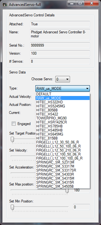
Open the Phidget control panel and open the GUI for the servo controller.
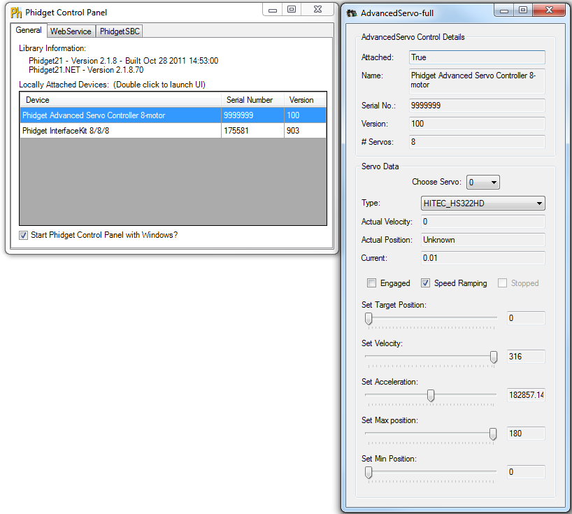
Plug your servo in set the Minimum Pulse Width to ___ and the Maximum Pulse Width to the maximum pulse width limit described in the API for your device.
Set Position at Min and Position at Max to match the Min Pulse Width and Max Pulse Width, respectively. This will allow you to control the actual microsecond pulse width sent to the servo.
Starting with the target position slider approximately in the middle, engage the motor. The motor should move into position.
Move the target position slider to the left until the motor stops turning. The servo should stop before the slider hits its limit. Take note of the value at which the motor stops, the more precise you can be the better, but the nearest multiple of 10 is usually sufficient. This is the minimum pulse width value and will be used later.
Move the slider to the right and again take note of where the servo stops turning. This will be the maximum pulse width value.
Using a protractor, measure the actual range of movement of the servo motor. This should be close to the rated value but it will likely not match exactly. Accuracy to the nearest degree is good enough.
To do this start with the motor at one extreme. Mark a spot on the motors output shaft in line with 0 degrees and then rotate the motor to its other extreme. Take the value of where the mark you made now rests and that is the motor’s full range of motion. For linear actuators, retract the arm all the way, mark the position of the end of the arm, extend it to its maximum length, and then measure the distance in millimeters from the end of the arm to the old position. In either case, the difference between the positions will correspond to the difference between the Position at Min Pulse Width and the Position at Max Pulse Width.
Finally, check the motor’s data sheet to see the maximum rated velocity. Now that all the measurements have been taken, you can calibrate for the servo.
To test your calibration parameters:
Type your new parameters into their respective boxes in the Motor Calibration box, and type Apply.
Next, set the Velocity slider to the rated velocity of the motor.
The program is now calibrated to the servo motor.
For example:
The HITEC HS-322HD used in testing has the following parameters:
| Argument | Value |
|---|---|
| Min Pulse Width | 540 |
| max_us | 2370 |
| degrees | 180 |
| velocity_max | 316 |
So for example, in C# to initialize the specific HS-322HD tested the following change would be made to the
RCServo example code in the servo_attach function:
        void servo_attach(object sender, AttachEventArgs e)
        {
            ...
            //Set the individual servo parameters
            servo.MinPulseWidth = 540;
            servo.MaxPulseWidth = 2370;
            servo.MinPosition = 0;
            servo.MaxPosition = 180;
            servo.VelocityLimit = 316;
            ...
        }
Your program has now been calibrated to your servo motor. You can get calibration parameters for multiple motors and use all of them in one program should you require it.