Rotary Motion Guide
Introduction
In rotary systems, you have a rotating shaft which applies torque to do work. Typically this shaft is turned by an electric motor of some kind and then, through a series of belts/chains/couplers transmits that power to a final output shaft or arm or wheel which accomplishes the desired task. Why not just use the output shaft of the motor directly? There are two main reasons:
- You might want to gear the motor down further to increase the torque available by using pulleys or sprockets of differing sizes.
- The shaft on the motor itself isn't really designed for forces other than torque. It is difficult to put anything of significant size on the shaft without putting too much overhung (radial) load on the shaft which will stall the motor.
As a result, the base of any rotary system is the rotating shaft. We have 4 sizes of shaft available: 8mm, 12mm, 17mm, and 25mm. The 12, 17, and 25mm shafts also have a variant available with a keyway machined in the length of the shaft if you don't want to machine it yourself. These shafts need to be suspended on bearings, we do not sell any bearings currently but they are commonly available components that you can find locally. For the larger shaft sizes (17 and 25mm) we recommend using steel bearing housings.
Motors
Every system will need a motor or else there will be no motion (without external input). We offer a wide selection of motors of a number of different types that would all be suitable for rotary systems. For more information on this you can check out our guides for DC motors and Stepper motors.
Pulleys/Timing belts
A belt is simply a loop of tough, flexible material such as rubber and kevlar with a series of teeth that mesh with the teeth on specially designed pulley wheels to synchronize two (or more) rotating shafts. Belts are a cheap option for shafts that are not axially aligned and tend to run quietly and smoothly. Belts are typically tensioned either by adjusting center to center distance between pulleys or via a tensioner/idler pulley. This leads to very low backlash and a high efficiency (as high as 98%).
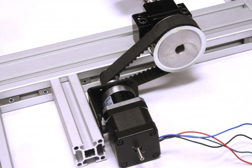
We have two types of belts available, GT2 (6mm wide) and GT5 (15mm wide). Each comes in loops of varying circumferences. The GT2 belts are rated for 6lbs of working tension while the GT5 are rated for 100lbs. Belt systems are fairly simple, you have 2 or more pulleys and a belt that goes around all of them. One of the pulleys is driven by your motor and the other(s) are either connected to your load or in the case of an idler pulley are simply free spinning to act as a tensioner for the belt. For example, here is a system that uses a belt to transmit power form a stepper motor to a ball screw:
Chain/Sprockets
Pretty much everyone has at least seen a chain system in their life in the form of a bicycle. This system of course is driven by human input rather than a motor. Automated systems behave no differently though, you have several sprockets, and chain that wraps around them. One sprocket is driven and the others perform work on the load. Chain tends to be noisier than belts and cannot be tensioned as tightly meaning there is a bit more backlash inherent in the system. In exchange though, chain can move much heavier loads for their size.
We sell ANSI#25 and #40 chain and sprockets (that is 0.25" pitch and 0.5" pitch). The #25 is rated for 100lbs of working tension while the #40 is rated for 800lbs. Chain is sold by the meter and you can form closed loops of any length you'd like with the link kits that we sell.
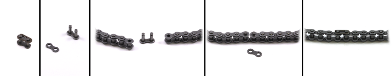
There are two ways to connect chain, you can either use a hammer and a pin of some kind to knock out one of the pins which you can then connect up with an offset link:
The other way is if you have a chain breaker tool you can remove an entire link properly and can use a normal split link. This process is a bit more tricky but it is stronger over all and will increase the length of the chain by a standard amount unlike the offset link which adds a sort of half link to your total length. To use a split link you must remove the snap ring and the top plate, then slot it into the chain and replace them both. For example:
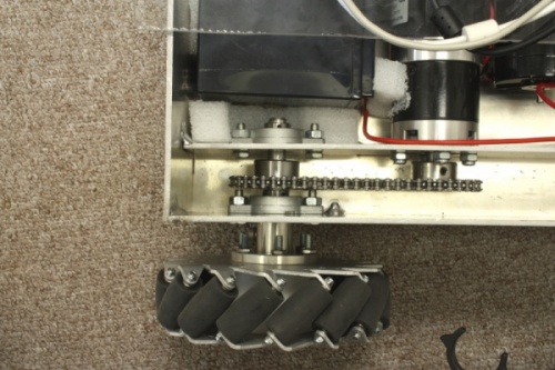
A good example of a chain system is our MURVV robot. Here is how it's drive mechanism works:
Worm Gearboxes
In general, worm gearboxes are just another type of gearbox that can be fitted to a motor. The main benefit of a worm drive is that it is all but impossible to back drive even when not powered. This is due to the steep angle used by the gears as they mesh together. As a result, this type of gearbox is not the most efficient. There is a lot of frictional loss at the mesh point and they will tend to run hot. That being said, in the context of the worm drives we sell, they are a means to substantially increase the output torque of our larger motors for applications where maximum strength is required. All our worm gearboxes have a 30:1 gear ratio and since the bearings built into the gearbox can handle much higher axial and radial loads that motors themselves you can easily direct drive very large loads from these gearboxes without having to set up an external mechanism.
Bearings
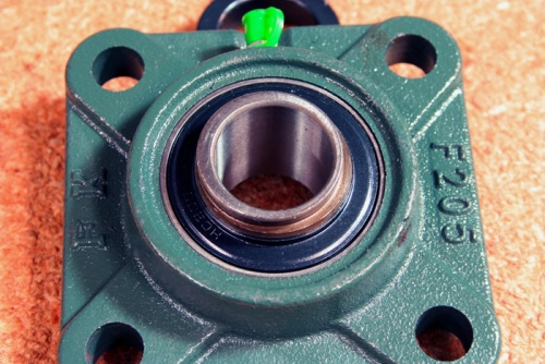
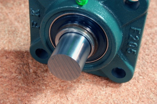
For the smaller bearings, installation is fairly straight forward. Simply mount the bearing onto your surface, slot the shaft in and tighten the set screws. However, for our larger bearings (12mm, 17mm and 25mm) there is a different system used known as an eccentric locking collar or eccentric collar lock. This is relatively simply to set up but you may not have seen this style of attachment before so lets have a look quickly at how it works and how to install it.
The locking mechanism works by putting a slightly eccentric hole in the bearing and using a collar with a matching hole. This way, when the collar is twisted on the shaft it will bind. Step by step:
Notice how the wall of the bore is thinner on the right side than the left. This is also true of the collar which slides over the top of the shaft once it is in position. Insert the shaft in the bearing unit to the desired position:
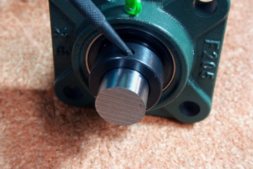
Next, put the collar onto the shaft and slide it down to the bearing. Turn the collar slowly until it seats on the lip of the bearing (i.e. the eccentricity of the holes lines up). Now you will want to tighten the collar by hand by turning it like you would a threaded cap. You will notice that it will bind by turning it in either direction within 180°. Be sure to turn the collar in the same direction the primary direction of rotation for the shaft in operation will be. Once the collar is tight, you will need to use a punch and a hammer to tighten it the last bit. Find the dead hole in the collar (not the set screw) and insert your punch. Angle the punch against the wall of the direction you have tightened the collar and give it a few solid taps with the hammer:
Now just tighten the set screw to ensure it doesn't loosen up with use and you are finished. To quickly demonstrate here is a video, note that I do not tighten the set screw in this video but that is straight forward enough so it was left out: