Improving Phidgets Hardware Reliability
This document is meant to be used as a first line of defense by customers who find their Phidgets system is not stable, or who are designing a system and want to understand common sources of instability.
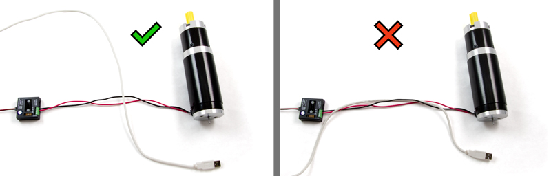
The most common issue is device resets. A reset is commonly seen as a Detach event, usually followed by an Attach event. Your program should be written to handle these events cleanly, and you can easily test your program by forcing these events to occur by unplugging and replugging the USB or VINT cable during normal operation. Our recommended best practice is to cleanly handle detaches in your code, AND resolve the source of detaches.
Device Resets (Due to Low USB Voltage)
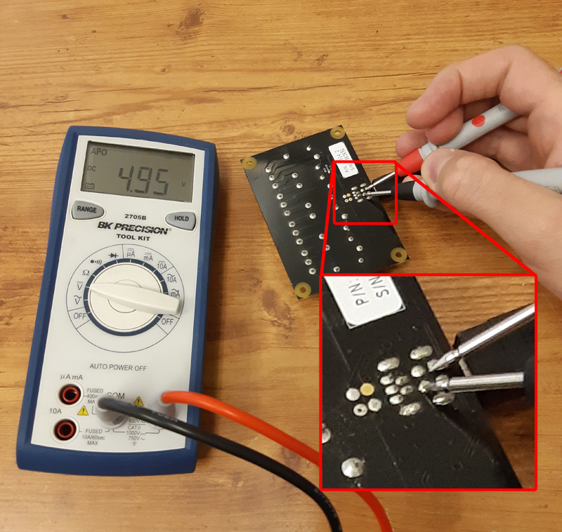
The most common source of detaches is low USB voltage. These detaches are deliberately executed by the USB Phidget device to guard against any possibility of erratic behaviour. Multiple factors are at play, and usually several are required to create a low voltage situation. If you suspect this issue, debugging begins by setting up the worst case scenario for power consumption (turn on relays, etc) and measuring USB voltage on the Phidget that is detaching.
Specific USB Phidget
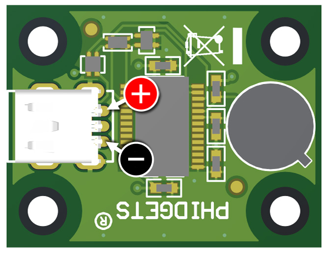
Older designs of Phidgets that use Cypress microcontrollers need to set a very high reset threshold to guard against erratic behaviour; the device will reset (detach) if USB power drops below 4.55 volts. A complete list of Phidgets with Cypress microcontrollers follows (omitting the revision number, this applies to all devices with the base part number). Click on the [Expand] next to your Phidget listed here to see where to measure with a multimeter if you suspect an issue.
1002 - PhidgetAnalog 4-Output
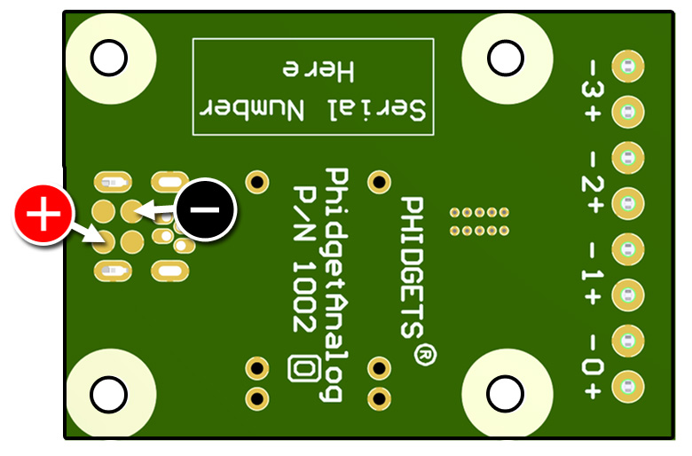
On the underside of the board, test the USB connector's power and ground pins as pictured.
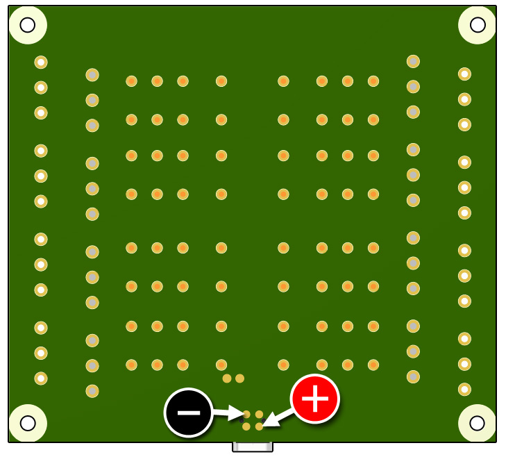
1010 - PhidgetInterfaceKit 8/8/8 Mini-Format
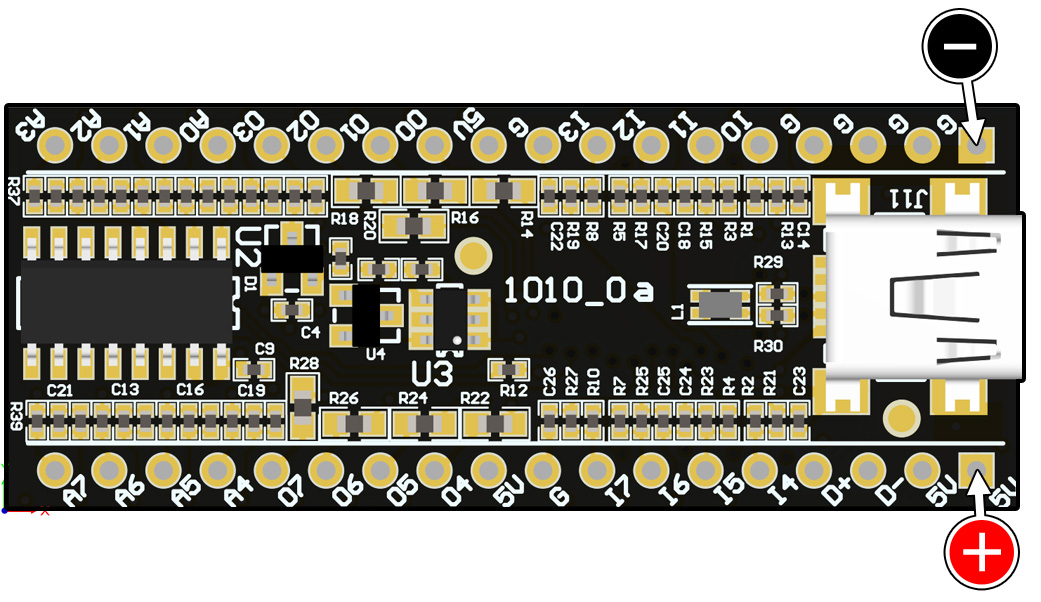
Test any 'G' pin and any '5V' pin.
1011 - PhidgetInterfaceKit 2/2/2
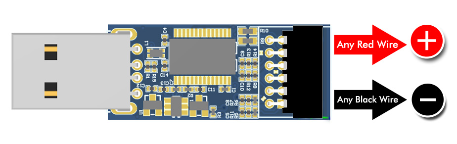
Connect the cable to the 1011 and measure between any red wire and any black wire.
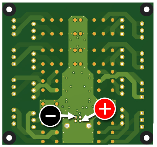
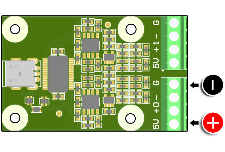
1012 - Phidget InterfaceKit 0/16/16
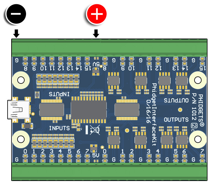
Test any '5V' and any 'G' pin.
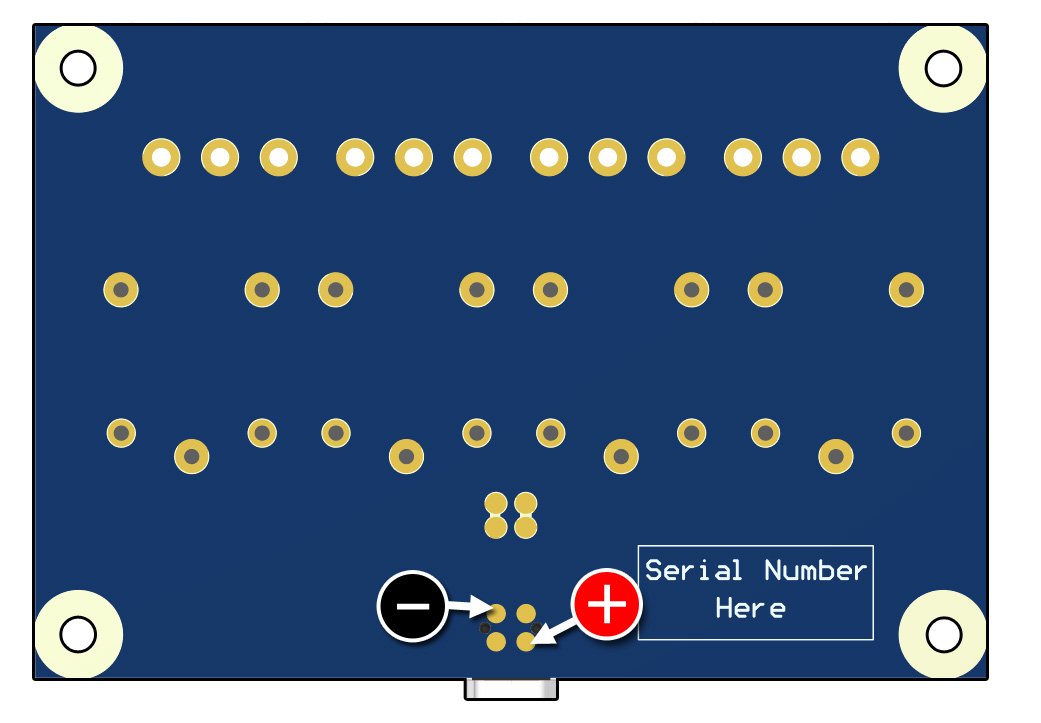
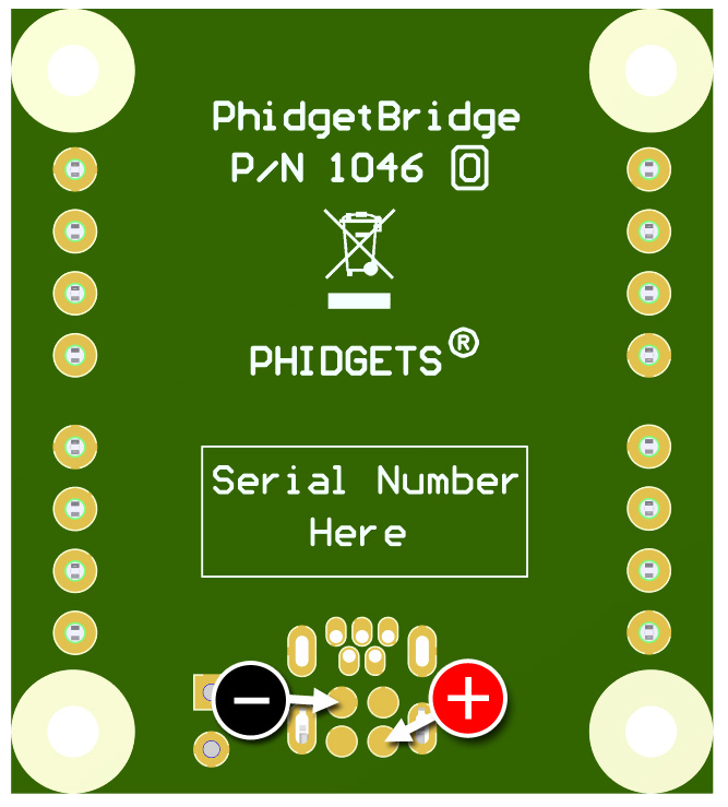
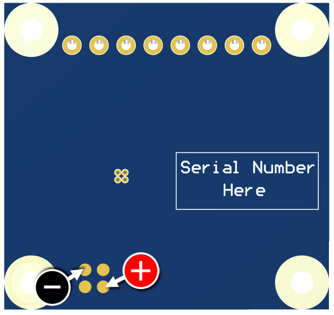
On the underside of the board, test the USB connector's power and ground pins as pictured.
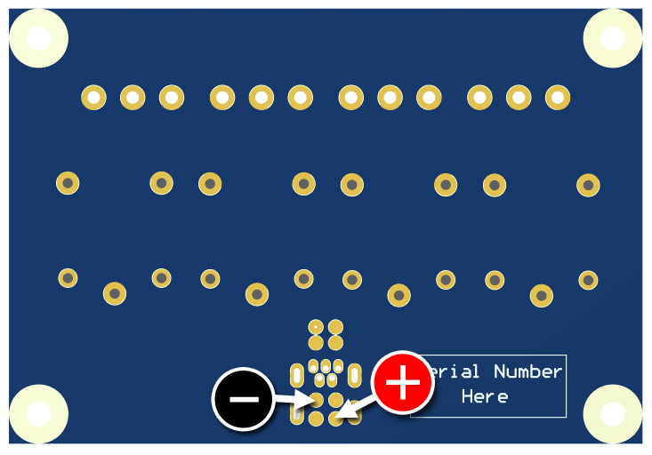
On the underside of the board, test the USB connector's power and ground pins as pictured.
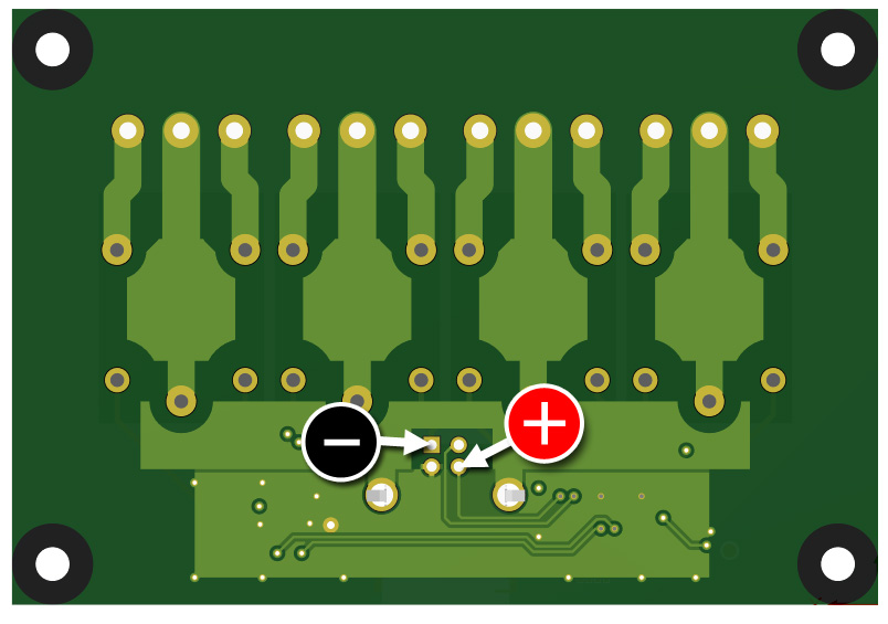
On the underside of the board, test the USB connector's power and ground pins as pictured.
On the underside of the board, test the USB connector's power and ground pins as pictured.
On the underside of the board, test the USB connector's power and ground pins as pictured.
1018 - Phidget InterfaceKit 8/8/8
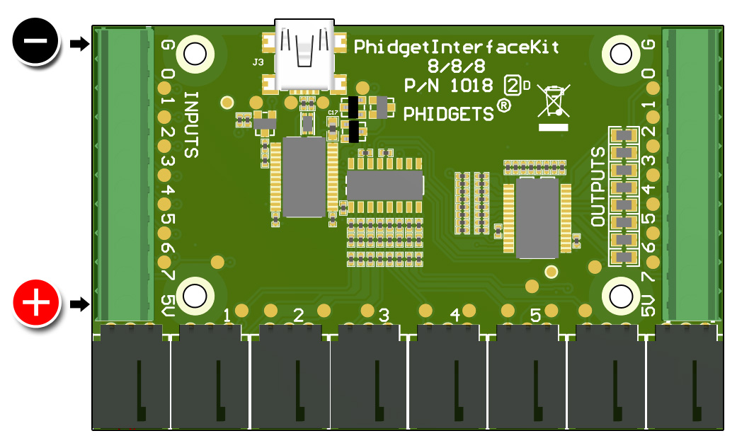
Test any '5V' and any 'G' pin.
1040 - PhidgetGPS
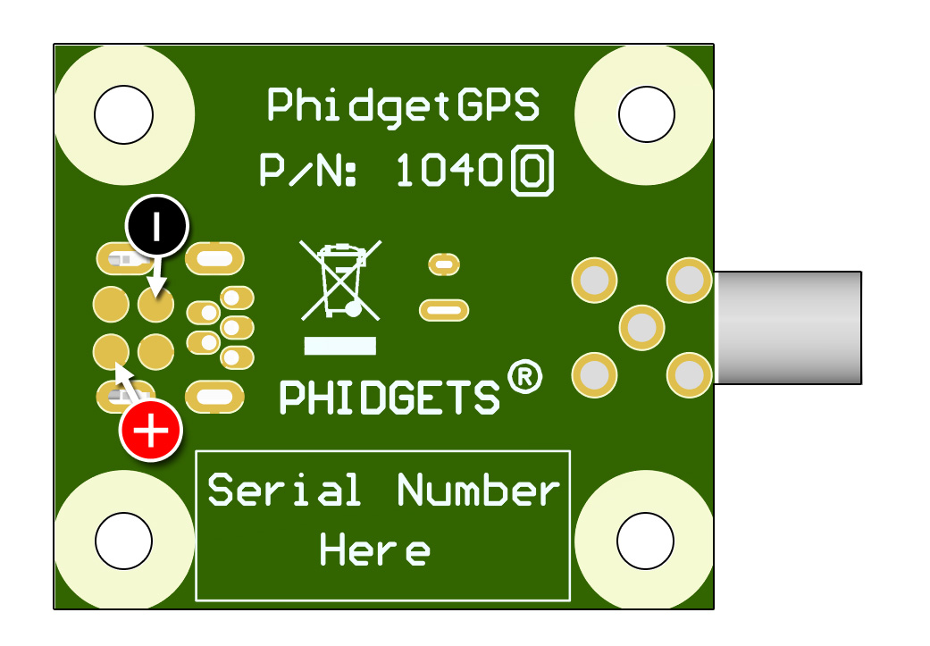
On the underside of the board, test the USB connector's power and ground pins as pictured.
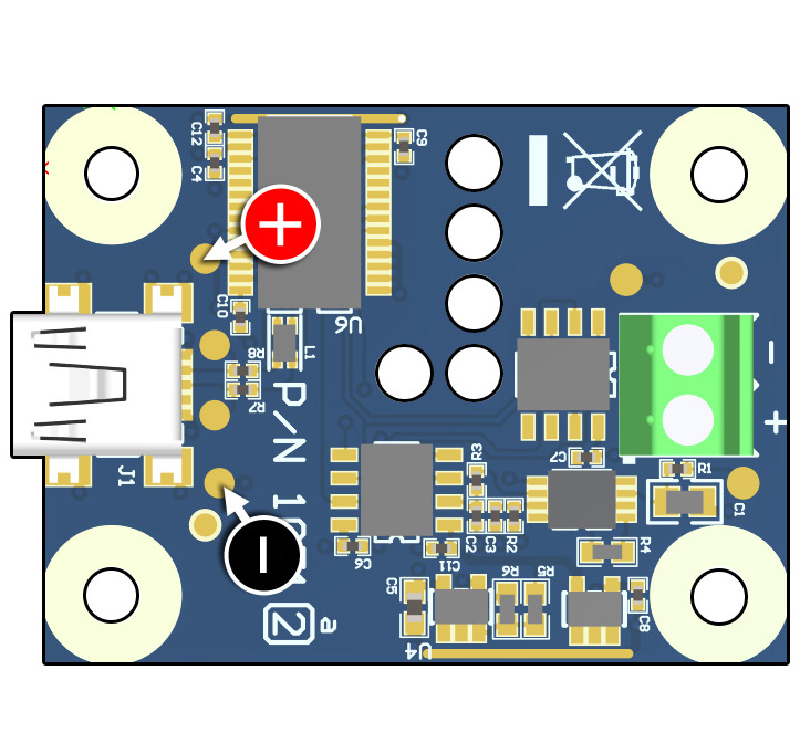
On the top of the board, test the USB connector's power and ground pins as pictured.
On the top of the board, test the USB connector's power and ground pins as pictured.
On the top of the board, use the test points as pictured.
On the underside of the board, test the USB connector's power and ground pins as pictured.
On the underside of the board, test the USB connector's power and ground pins as pictured.
1047 - PhidgetEncoder HighSpeed 4-Input
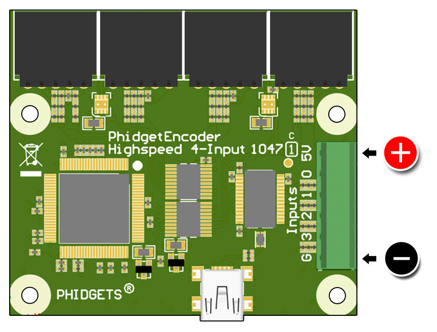
Test the '5V' and 'G' pin.
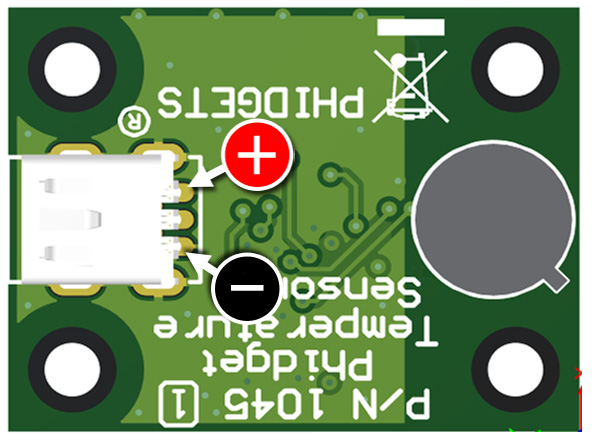
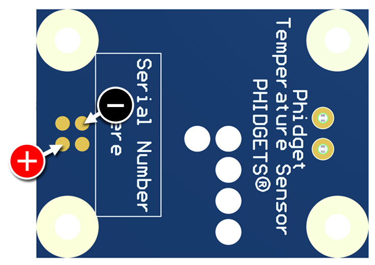
1048 - PhidgetTemperatureSensor 4-Input
On the underside of the board, test the USB connector's power and ground pins as pictured.
On the top of the board, use the test points as pictured.
On the underside of the board, test the USB connector's power and ground pins as pictured.
On the underside of the board, test the USB connector's power and ground pins as pictured.
1054 - Phidget FrequencyCounter
Test any '5V' and any 'G' pin.
1055 - PhidgetIR
On the underside of the board, test the USB connector's power and ground pins as pictured.
1057 - PhidgetEncoder HighSpeed
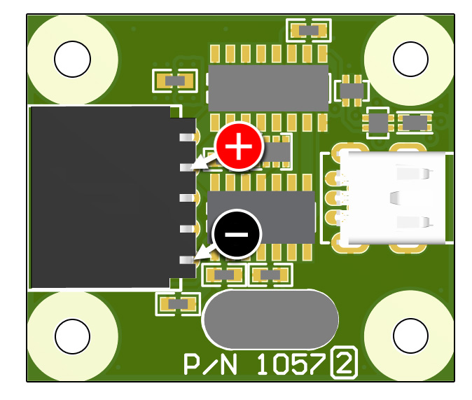
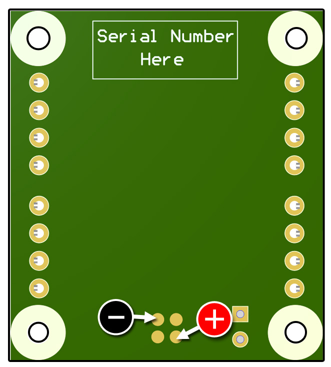
Test the second and fifth pins on the encoder connector, either where the bent pin enters the plastic housing on top, or where the pins are soldered on the underside.
On the top of the board, test the USB connector's power and ground pins as pictured.
On the underside of the board, test the USB connector's power and ground pins as pictured.
On the top of the board, test the USB connector's power and ground pins as pictured.
On the underside of the board, test the USB connector's power and ground pins as pictured.
On the top of the board, test the USB connector's power and ground pins as pictured.
On the underside of the board, test the USB connector's power and ground pins as pictured.
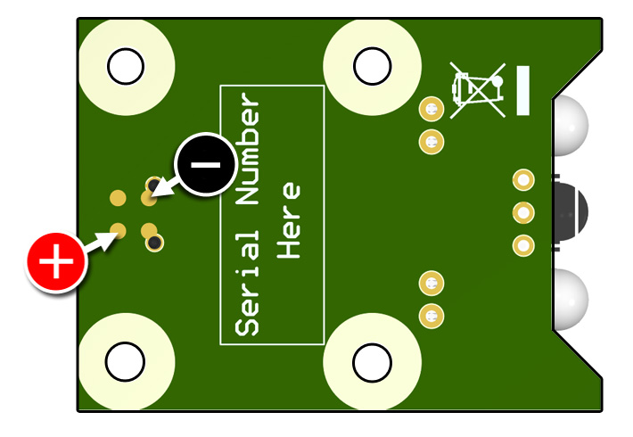
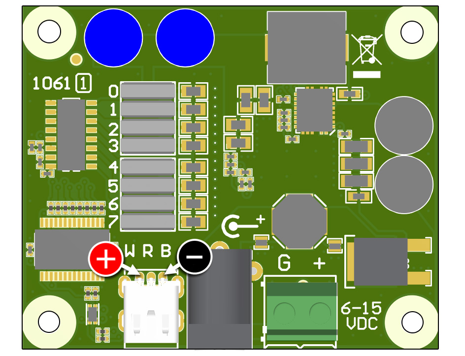
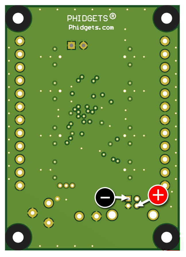
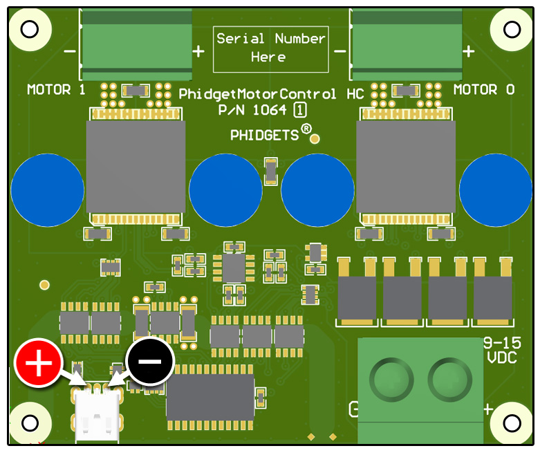
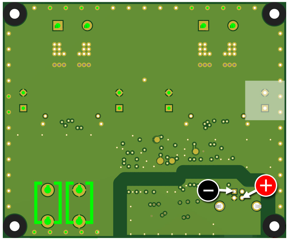
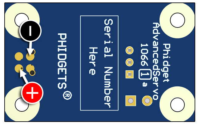
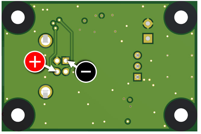
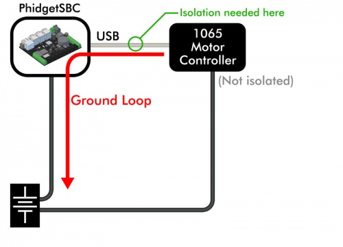
1065 - PhidgetMotorControl 1-Motor
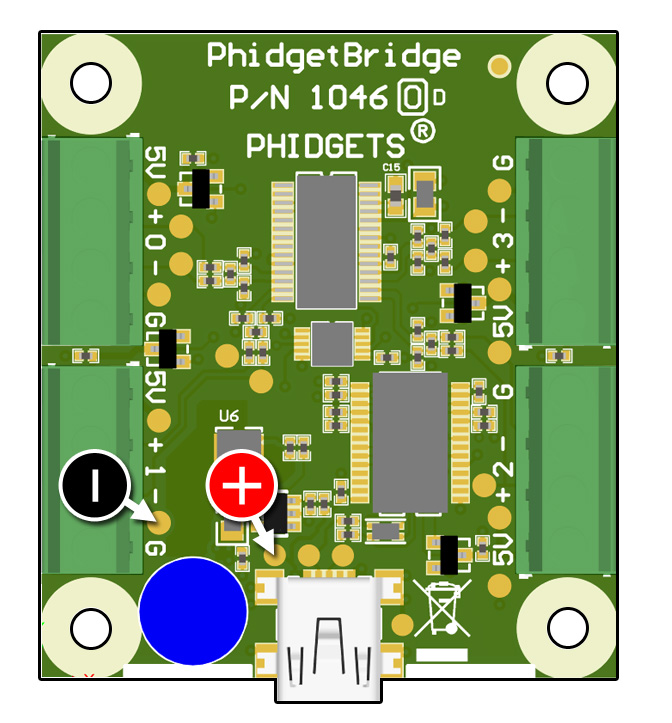
Test the 'G' pin and '5V' pin.
On the underside of the board, test the USB connector's power and ground pins as pictured.
On the underside of the board, test the USB connector's power and ground pins as pictured.
USB Phidgets other than those listed here have a much lower reset threshold, and would require a very unlikely scenario to produce a low voltage reset.
USB Cable
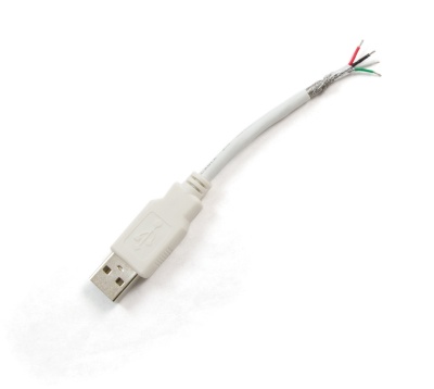
Some USB Cables have thin power conductors or a poorly bonded shield braid. This is unlikely to be an issue on a 30cm cable, but a longer USB cable needs to be properly built.
The maximum length for a USB cable is 5 meters. We don’t recommend using USB extenders, repeaters, or USB over Ethernet products because they are often a source of instability. Implementing control of Phidgets over long distances or wireless is best done with the HUB5000 if your system is exclusively VINT, or the SBC3003 if you also need to use some USB Phidgets.
USB Supply Voltage
Unpowered USB hubs can really reduce the USB supply voltage. The power to the hub is shared across multiple devices, and the hubs will often use inexpensive passive fuses that strongly reduce the voltage as current increases. Early versions of the Raspberry Pi would typically provide such a low voltage that many USB Phidgets were prevented from working at all. If you suspect this is a problem in your system, try using an externally powered USB hub.
Pulsed Power Consumption
Some sensors and controllers produce heavy spikes of power consumption, which can cause the USB voltage to flicker.
- Motors that run from USB power will consume much more power during fast acceleration from standstill, and stall conditions. Luckily, most Phidget motor controllers are externally powered (the 1066 is a notable exception).
- Infrared distance sensors (e.g. Sharp Distance Sensors, 1103) will typically flash an LED with a pulse of current. The Sharp Distance Sensors have such an extreme pulse of power that the 1101 adapter board was specifically designed to buffer this pulse. The 1103 uses much smaller pulses, but still requires care if several of them are running on a single USB interfacekit.
You should only be concerned if the product documentation for your device mentions a high pulse load, and you are deploying multiple devices. Assurance that your devices are well above the reset voltages can be done in several ways:
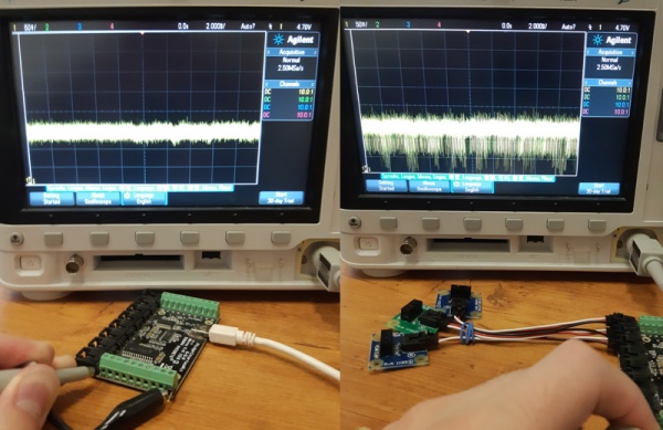
- Monitor USB voltage during operation with an oscilloscope. Make sure USB stays above 4.75 volts (if your USB device uses the Cypress Microcontroller, listed above)
- Change the USB cable to a longer cable, test the system for several hours, and if there are no issues, swap back to a shorter cable for deployment.
- Call application engineers at Phidgets Inc.
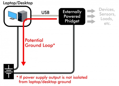
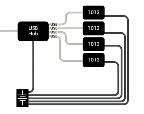
Device Resets (Due to Grounding Issues)
Heavy flows of current on USB cables can reduce effective USB voltage, and in severe cases, interfere with signaling. Products more likely to experience problems are non-isolated USB Phidgets that connect to external power supplies or externally powered loads. Examples of USB Phidgets that are more likely to be wired in a way that produces issues are:
Don’t panic! Just because there is a power supply or battery in your system, doesn’t mean grounding is a problem.
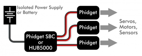
- If your power supply or battery is only attached to this device, grounding will not be a problem.
- If your power supply is shared with other devices, but at most one device is not isolated, you cannot have a grounding problem.
- If you have multiple non-isolated loads that share a power source - look out.
Here's a few scenarios that you might find in your system. Note that only the ground connections are shown in these diagrams for simplicity's sake.
|
Scenario A:
|
|
Scenario B:
|
|
Scenario C:
|
|
Scenario D:
|
Device Resets (Due to Cable to Cable Interference)
Wrapping cables together to create huge bundles may look neat and attractive, but it can increase electrical noise. Most wiring doesn’t have enough noise to cause problems, but here is a breakdown of some typical cables:
| Cable | Noise Generation | Noise Vulnerability | Comments | |
|---|---|---|---|---|
| USB | Low | Low | USB and Ethernet are well balanced electrically, able to function in reasonably strong interference and not cause problems for other cables in close proximity to them. | |
| Ethernet | Low | Low | ||
| RF (Coaxial) Cables | Low | High | RF (Coax) Cables are very unlikely to cause interference, but are vulnerable if bundled tightly with cables that are creating even moderate interference. | |
| Digital Input or Analog Voltage Signals | Low | High | Unlikely to cause interference, but can very easily pick up interference. This type of signal can easily be shielded (we sell multi-conductor shielded cable), but can also be easily filtered by the product receiving the signal. Fortunately, the designers at Phidgets have long since learned how to properly filter incoming signals. | |
| Power Distribution Lines | Moderate | Low | Unlikely to be affected by any interference received. Noise levels are typically in the hundreds of millivolts - possible to interfere with other cables in the vicinity, but should not be noisy enough to cause communication resets on buses like USB. | |
| Motor Controller Outputs | High | Low | Heavy generators of noise. The wires between a stepper motor and its controller (running at 24 volts in our example) look like 24 volts of high frequency noise to other wires in the vicinity. | |
| PWM Power Signals and Outputs | High | Low | Pulse-width modulated outputs from boards like LED Controllers (1032, LED1000) and generic controllers like REL1101 also produce very large amounts of noise at high frequencies. |
Wires prone to high noise emissions should be kept short (well less than a meter) and not be routed closely with other wiring. USB and VINT are able to function in close proximity to these noise sources, especially for prototyping. When deploying systems, arrange your data cables perpendicular to power cables to minimize crosstalk to buy extra margin, just to be safe.
Device Resets (Caused by Sharp “Cracks” of Interference)
Static Discharge
People are commonly charged with upwards of tens of thousands of volts of static electricity as we walk across carpet, get in and out of our cars, etc. We are effectively high voltage capacitors that occasionally discharge into the electronics we touch. When electronics designers plan for ESD (Electrostatic Discharge), the first priority is to ensure the survival of the circuit. The second priority is to cleanly recover in a reasonable amount of time.
Any circuit designer worth their salt can design a smallish circuit board like found in most Phidgets to cleanly ride through an extreme electrical shock like an ESD event. The challenge is usually on the communication buses, like USB. The system response to this burst of sudden errors will be to reset the device. This is a major reason why we recommend our customers code to cleanly handle device detaches/attaches. All our devices are designed and tested to reattach cleanly, but application code has to handle this when it happens.
Anything else that generates a spark
Plugging in an extension cord, power supply, or opening/closing a mechanical relay will create a small spark, and a blast of interference. Under normal conditions, a system built from Phidgets will easily ride through, automatically correcting any communication errors. At worst, devices will detach/re-attach.
In our experience, poor shielding will make a system much more vulnerable. Metal in close proximity to cables will pick up the interference, and strongly amplify the noise into the cables. If metal enclosures are used, they must be designed to operate as a Faraday cage - particularly in the range of 10-200Mhz. This is well outside the scope of this document - our generic recommendation is to shield cables if necessary, and not attempt to shield Phidgets and the system as a whole.
In our experience, the shield of a cable must be connected to ground on each end. This recommendation is exactly opposite to what many engineers have learned. In fact, the original USB 1.0 specification called for not connecting USB shield to ground at the device - they have since changed their tune!
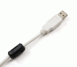
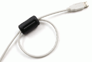
Use of Ferrite Beads
Ferrites are useful for damping out electrical ringing on cables. Every cable will have preferred frequencies - mostly determined by cable length. External noise couples into wires, providing the stimulus for the ringing. The longer ringing carries on, the higher the chance of interrupting communication and triggering a device reset. Standard USB Cables already have ferrite beads installed- adding more will not hurt, but this is typically not required.
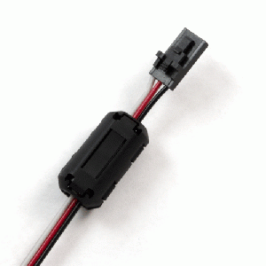
Ferrite beads will not help to reduce noise on wires carrying PWM signals or motor control. The noise is far too strong for ferrites to help. Adding ferrites to power distribution wires will reduce noise, and should be placed close to the source of interference. Only do this if there are specific symptoms, for example interference on a radio. Phidgets Inc. is very careful to filter power supply noise created by our devices before the noise has a chance to leave the board.
In conclusion - Ferrites beads are not normally required on a system built with Phidgets. Use ferrites on communication lines if devices are detaching because of electrical noise.
General Recommendations
Prototype and Lab bench systems
Just build it. Chances are very high you won’t have any problems. Use VINT devices as much as possible, especially for devices that need external power. If there is any chance a VINT device will benefit from isolation, then we’ve already built it in. Avoid the temptation to tidy up all the cables into bundles.
Production systems

Use VINT devices as much as possible, especially for devices that need external power. If there is any chance a VINT device will benefit from isolation, then we’ve already built it in. Be careful with PWM outputs (including LEDs), motor outputs. If possible, keep these wires short, and away from other signals. Bundling wires that aren’t being deliberately pulsed is usually ok. Don’t spend extra for metal enclosures unless you have expertise with shielding. Minimize USB cable lengths, by buying cables that are the minimum length for your application. Cutting and resoldering a USB cable is a bad idea.
If you are deploying USB Phidgets that use the Cypress Microcontroller (listed earlier), maximize the USB power consumption in the system, and check USB voltage at each Phidget. If you see a voltage less than 4.75V, contact us.
Use a BBQ lighter to create electrical interference to test if your system can recover gracefully. Don't let the spark directly contact the system though- these sparkers generate a huge power spike that can damage components on the board.
Test your code by unplugging and replugging devices, and cycling external power (if that can be done without bringing down the entire system)