|
|
| (33 intermediate revisions by 4 users not shown) |
| Line 1: |
Line 1: |
| | __NOINDEX__ |
| | <metadesc>The PhidgetSpatial 3/3/3 has a 3-axis accelerometer, gyroscope and compass and connects to your computer via USB.</metadesc> |
| | [[Category:UserGuide]] |
| ==Getting Started== | | ==Getting Started== |
| | {{UGIntro|1056}} |
| | *[{{SERVER}}/products.php?product_id=1056 1056 PhidgetSpatial 3/3/3] |
| | *USB cable and computer |
|
| |
|
| ===Checking the Contents===
| |
| {{UGbox|
| |
| '''You should have received:'''
| |
| * A PhidgetSpatial 3/3/3
| |
| * A Mini-B USB cable
| |
| |||}}
| |
|
| |
|
| ===Connecting the Pieces===
| | Next, you will need to connect the pieces: |
| {{UGbox|
| | [[Image:1056_0_Connecting_The_Hardware.jpg|500px|right|link=]] |
| Connect the PhidgetSpatial 3/3/3 to your PC using the Mini-B USB cable.
| | # Connect the PhidgetSpatial to your computer using the USB cable. |
| |
| |
| [[File:1056_0_Connecting_The_Hardware.jpg|400px|link=]] | |
| ||}}
| |
|
| |
|
| ===Testing Using Windows 2000 / XP / Vista / 7=== | | <br clear="all"> |
| | | {{UGIntroDone|1056}} |
| {{UGwin}}
| |
| | |
| ===Running Phidgets Sample Program===
| |
| | |
| {{UGwin2|'''Spatial-full'''}} | |
|
| |
|
| {{UGbox|
| | ==Using the 1056== |
| Double Click on the [[File:Ph.jpg|link=]] icon to activate the Phidget Control Panel and make sure that the '''Phidget Spatial 3/3/3''' is properly attached to your PC.
| | {{UGcontrolpanel|1056}} |
| |[[File:1056_0_Control_Panel_Screen.jpg|400px|link=]]
| |
| | | |
| # Double Click on '''Phidget Spatial 3/3/3''' in the Phidget Control Panel to bring up Spatial-full and check that the box labelled Attached contains the word True.
| |
| # You can adjust the Data Rate by moving the slider.
| |
| # Move the 1056 board around and you should see the data change to reflect the change of position along the 3 axes.
| |
| |[[File:1056_0_Spatial_Full.jpg|400px|link=]]
| |
| }} | |
|
| |
|
| ===Testing Using Mac OS X===
| | {{ugAccelerometer|1056|}} |
|
| |
|
| {{UGmac|Phidget Spatial 3/3/3|Spatial-full}} | | {{ugMagnetometer|1056}} |
|
| |
|
| ===Using Linux===
| | {{ugGyroscope|1056}} |
|
| |
|
| {{UGlinux}} | | {{ugSpatial|1056}} |
|
| |
|
| ===Using Windows Mobile / CE 5.0 / CE 6.0===
| | {{ugAddressingInformation}} |
|
| |
|
| {{UGce}} | | {{ugUsingYourOwnProgram|1056}} |
|
| |
|
| ==Technical Details== | | ==Technical Details== |
|
| |
| ===3-Axis Accelerometer=== | | ===3-Axis Accelerometer=== |
| | | For more information on how to use the accelerometer, check the [[Accelerometer Guide]]. |
| For more information on how to use the accelerometer, check the [[Accelerometer Primer]]. | |
|
| |
|
| ===3-Axis Gyroscope=== | | ===3-Axis Gyroscope=== |
| | | For more information on the gyroscope, see the [[Gyroscope Guide]]. |
| For more information on the gyroscope, see the [[Gyroscope Primer]]. | |
|
| |
|
| ===3-Axis Magnetometer (Compass)=== | | ===3-Axis Magnetometer (Compass)=== |
| | The magnetometer reports the sum of all magnetic fields acting on the 1056 device. The earth's magnetic field is only one source that affects this measurement. In order to get accurate bearing data from the magnetometer (i.e. to find magnetic north as a compass) any interfering magnetic effects need to be calibrated out. For more information about calibration, see the [[#Magnetic Error Correction (Calibration)|section below]], or the [[Compass Guide]]. |
|
| |
|
| The magnetometer reports the sum of all magnetic fields acting on the 1056 device. The earth’s magnetic field is only one source that affects this measurement. In order to get accurate bearing data from the magnetometer - ie. to find magnetic north as a compass - any interfering magnetic effects need to be calibrated out.
| |
|
| |
|
| Any magnetic field that is stationary with respect to the 1056 device, and less than ± 3 Gauss, can be calibrated out of the magnetic field measurement. This includes both hard and soft iron effects caused by nearby ferrous and magnetic materials. Interfering magnetic fields that vary in strength and orientation with respect to the 1056 device cannot be easily calibrated out. | | Any magnetic field that is stationary with respect to the 1056 device, and less than ± 3 Gauss, can be calibrated out of the magnetic field measurement. This includes both hard and soft iron effects caused by nearby ferrous and magnetic materials. Interfering magnetic fields that vary in strength and orientation with respect to the 1056 device cannot be easily calibrated out. |
| | |
|
| |
|
| Magnetic field data will become unavailable for ~28ms every 2 seconds as the compass perform internal calibrations. During this time, polling the magnetic field will return EPHIDGET_UNKNOWNVAL, or throw an UNKNOWNVAL exception. The magnetic field data in the SpatialData event will equal PUNK_DBL. | | Magnetic field data will become unavailable for ~28ms every 2 seconds as the compass perform internal calibrations. During this time, polling the magnetic field will return EPHIDGET_UNKNOWNVAL, or throw an UNKNOWNVAL exception. The magnetic field data in the SpatialData event will equal PUNK_DBL. |
|
| |
| ====Magnetic Error Correction====
| |
|
| |
| In order to get numbers of useful accuracy from the 1056's compass you will need to provide calibration parameters. To make determining them easy, we distribute a program with our drivers that does this for you.
| |
|
| |
| '''To calibrate your compass:'''
| |
| [[image:calibration1.png|thumb|200px]]
| |
| *Navigate to the Phidgets installation folder on your computer. Open the 'examples' folder and find the Compass Calibrator program.
| |
| <br clear = "all">
| |
| [[image:calibration2.png|thumb|200px]]
| |
| *Start the program and find the link in the Settings/Status text box. Go to the website listed. (http://www.ngdc.noaa.gov/geomag-web/#igrfwmm)
| |
| <br clear = "all">
| |
| [[image:calibration3.png|thumb|200px]]
| |
| *Select your country and city. Click 'Get Location' and then 'Compute'. A table of values will show up in an overlaid window. The value you will need is the 'Total Field' value in nT.
| |
| <br clear="all">
| |
| [[image:calibration4.png|thumb|200px]]
| |
| *Enter the magnetic field value into the calibration program.
| |
| *Depending on what your application is this step as well as the next step might be a bit different. If you are intending on mounting the 1056 onto a large vehicle such as a car then you should mount the 1056 securely to the vehicle in its final intended position then check the 2-axis bubble, click the 'Start' button.
| |
| *If you are using a smaller, more easily handled vehicle such as a small robot (something you could physically pick up) you will mount the 1056 and use the 3-axis calibration instead. Click 'Start'.
| |
| <br clear="all">
| |
| [[image:calibration5.png|thumb|200px]]
| |
| *Rotate the compass around (including whatever equipment you have mounted it to) such that the red dots being generated on screen outline as much of a full sphere (in 3-axis) as possible. This will take several minutes. Being perfect is not necessary but try to be as thorough as time permits. Once done, click stop.
| |
| *If you are in a large vehicle, you will be aiming to fill out a disc instead of a sphere. This can be done by simply driving around for a few minutes making sure to do complete <math>360^{o}</math> turns in the process.
| |
| <br clear="all">
| |
| [[image:calibration6.png|thumb|200px]]
| |
| *Take the parameters displayed in the text box and use them for your compass. For example in C#:
| |
|
| |
| <div style="background-color: #f3f3f3; border-color: #1c9edb; border-width:1px; border-style: dashed;">
| |
| <font size="3">
| |
| <source lang=CSharp>
| |
| setCompassCorrectionParameters(0.51075, 0.18820, -0.07456, -0.02209, 1.87163, 1.87640, 2.12565, -0.04000, -0.04084, -0.03552, 0.09073, -0.04258, 0.11056);
| |
| </source>
| |
| </font>
| |
| </div>
| |
| <br clear="all">
| |
|
| |
|
|
| |
|
| ====Finding North====
| | {{UGC-CompassCal}} |
| The three axis magnetometer data can be used, along with pitch and roll angles calculated from the accelerometer, to find a magnetic bearing - ie. as a compass. In order for the compass to be accurate at all, calibration must have been done to factor out hard and soft iron offsets.
| |
|
| |
|
| The magnetic field is represented as a vector. If the 1056 is completely level with respect to gravity, then we can calculate magnetic bearing easily by looking at the x and y components of the vector, which simply represents an angle between 0 and 360 degrees on the unit circle.
| |
|
| |
| However, when the board is not level, the magnetic field vector components in each axis will be skewed, or is other words, what we need to know is the magnetic field with respect to the earth frame, and what we have is the magnetic field with respect to the 1056, which is rotated with respect to the earth. What needs to be done is to rotate the magnetic field vector back into the earth frame, we can then use the x-y components to again determine bearing. The easiest way to do this is to find the board pitch and roll angles using the accelerometer, and then build a rotation matrix using these angles to rotate the magnetic field vector into the earth frame (ie aligned with gravity). This is demonstrated in the C# and Cocoa examples.
| |
|
| |
|
| ====Further Reading==== | | ====Further Reading==== |
| | For more information on magnetometers (compasses), see the [[Compass Guide]]. |
|
| |
|
| For more information on magnetometers (compasses), see the [[Compass Primer]].
| | {{UGnext|}} |
| | |
| ==API==
| |
| {{UGapih}} | |
| | |
| ===Data Structures===
| |
| <b>
| |
| SpatialData {
| |
| :double acceleration[3];
| |
| :double angularRate[3];
| |
| :double magneticField[3];
| |
| :Timestamp time;
| |
| };
| |
| | |
| Timestamp {
| |
| :int seconds; -time since attach event
| |
| :int microseconds; -time since last second
| |
| };
| |
| </b>
| |
| | |
| The SpatialData Structure is used by the OnSpatialData event. This contains acceleration data, angular rate data, magnetic field data, and a timestamp. The timestamp is an accurate measurement streamed from the hardware,and can be trusted over a local software timestamp. This timestamp is generally used for integrating angular rate into a heading over time.
| |
| | |
| ===Properties===
| |
| {{UGapi|int AccelerationAxisCount() [get] : Constant <nowiki>=</nowiki> 3
| |
| |Returns the number of axes the PhidgetSpatial can measure acceleration on.
| |
| }}
| |
| | |
| {{UGapi|double Acceleration (int AxisIndex) [get] : Units <nowiki>=</nowiki> g (standard gravity <nowiki>=</nowiki> 9.81m/s²)
| |
| |Returns the acceleration of an axis. At a standstill each axis will measure between -1.0 and 1.0 g’s depending on orientation - the effect of gravity. This value will always be between AccelerationMin and AccelerationMax.
| |
| }}
| |
| | |
| {{UGapi|double AccelerationMax (int AxisIndex) [get] : Constant <nowiki>=</nowiki> 5.1g
| |
| |Returns the maximum acceleration value that this axis will report. Acceleration can be accurately measured up to 5.0g - any value past this will be reported as 5.1g, which represents saturation. If the acceleration data is equal to AccelerationMax, it should be treated as suspect, as the real acceleration could be far greater than the reported number.
| |
| }}
| |
| | |
| {{UGapi|double AccelerationMin (int AxisIndex) [get] : Constant <nowiki>=</nowiki> -5.1g
| |
| |Returns the maximum negative acceleration value that this axis will report. Negative acceleration can be accurately measured up to -5.0g - any value past this will be reported as -5.1g, which represents saturation. If the acceleration data is equal to AccelerationMin, it should be treated as suspect, as the real acceleration could be far greater than the reported number.
| |
| }}
| |
| | |
| {{UGapi|int GyroAxisCount() [get] : Constant <nowiki>=</nowiki> 3
| |
| |Returns the number of axes the PhidgetSpatial can measure angular momentum on.
| |
| }}
| |
| | |
| {{UGapi|int AngularRate(int AxisIndex) [get] : Units <nowiki>=</nowiki> °/s (degrees/second)
| |
| |Returns the angular momentum on an axis. This value will always be between AngularRateMax and AngularRateMin. If the value is equal to AngularRateMax or Min, the data should be treated as suspect, as the sensor may be saturated.
| |
| }}
| |
| | |
| {{UGapi|int AngularRateMax(int AxisIndex) [get] : Constant <nowiki>=</nowiki> 400°/s
| |
| |Returns the maximum angular momentum that this axis will report. If the angular rate is reported as 400°/s, this
| |
| should be considered saturated, and any heading integration will have errors.
| |
| }}
| |
| | |
| {{UGapi|int AngularRateMin(int AxisIndex) [get] : Constant <nowiki>=</nowiki> -400°/s
| |
| |Returns the maximum negative angular momentum that this axis will report. If the angular rate is reported as
| |
| -400°/s, this should be considered saturated, and any heading integration will have errors.
| |
| }}
| |
| | |
| {{UGapi|int CompassAxisCount() [get] : Constant <nowiki>=</nowiki> 3
| |
| |Returns the number of axes the PhidgetSpatial can measure magnetic field strength on.
| |
| }}
| |
| | |
| {{UGapi|int MagneticField(int AxisIndex) [get] : Units <nowiki>=</nowiki> G (gauss)
| |
| |Returns the magnetic field on an axis. This value will always be between MagneticFieldMax and MagneticFieldMin. If the reported value is equal to MagneticFieldMax or Min, the data should be treated as suspect, as the sensor may be saturated. Magnetic field measurements can be combined to calculate compass bearing (magnetic north).
| |
| | |
| :Magnetic field data will become unavailable for ~28ms every 2 seconds as the compass perform internal calibrations. When this happens this function will return EPHIDGET_UNKNOWNVAL, or throw an UNKNOWNVAL exception, depending on the API being used.
| |
| }}
| |
| | |
| {{UGapi|int MagneticFieldMax(int AxisIndex) [get] : Constant <nowiki>=</nowiki> 4.1G
| |
| |Returns the maximum magnetic field that this axis will report. Magnetic field strength can be accurately measured up to 4.0G - any value past this will be reported as 4.1G, which represents saturation.
| |
| If the magnetic field data is equal to MagneticFieldMax, it should be treated as suspect, as the real magnetic field could be far greater than the reported number.
| |
| }}
| |
| | |
| {{UGapi|int MagneticFieldMin(int AxisIndex) [get] : Constant <nowiki>=</nowiki> -4.1G
| |
| |Returns the maximum negative magnetic field that this axis will report. Magnetic field strength can be accurately measured down to -4.0G - any value past this will be reported as -4.1G, which represents saturation. If the magnetic field data is equal to MagneticFieldMin, it should be treated as suspect, as the real magnetic field could be far greater than the reported number.
| |
| }}
| |
| | |
| {{UGapi|int DataRate () [get,set] : Units <nowiki>=</nowiki> ms (milliseconds)
| |
| |Gets/sets the data rate. This is corresponds to the time interval at which SpatialData events will be fired. This is bound by DataRateMax and DataRateMin. When set to less then the maximum data rate, data is still sampled at the maximum rate, and averaged before being sent to the user. At data rates below 8ms, the data event will fire at 8ms intervals with an array of spatial data.
| |
| Supported data rates are: 4ms, 8ms and every multiple of 8 up to 1000ms (ie. 8, 16, 24, 32, etc). The default data rate is 8ms.
| |
| Data rate is limited to at most 16ms when opening over the Phidget Webservice. Actual data rate will depend on network latency.
| |
| }}
| |
| | |
| {{UGapi|int DataRateMax () [get] : Constant <nowiki>=</nowiki> 4ms
| |
| |The maximum supported data rate.
| |
| }}
| |
| | |
| {{UGapi|int DataRateMin () [get] : Constant <nowiki>=</nowiki> 1000ms
| |
| |The minimum supported data rate.
| |
| }}
| |
| | |
| ===Functions===
| |
| {{UGapi|void zeroGyro();
| |
| |Re-zeroes the gyroscope. This takes 1-2 seconds of gyro samples and uses this data as a new zero point. The 1056 must remain stationary during the zeroing process. The angular rate will be reported as zero during zeroing.
| |
| }}
| |
| | |
| {{UGapi|void setCompassCorrectionParameters(double magField, double offset0, double offset1, double offset2, double gain0, double gain1, double gain2, double T0, double T1, double T2, double T3, double T4, double T5);
| |
| |Sets correction parameters for the magnetometer. This can be used to correct for hard and soft iron offsets, bias errors in the magnetometer, etc. Generally useful for using the magnetometer as an electronic compass. The parameters can be determined from the Phidget supplied calibration program.
| |
| | |
| '''Parameters:'''
| |
| : '''magField:''' The reference field to use. Generally, use the local expected field strength, or 1.0.
| |
| : '''offset0,1,2:''' Applies offset to the compass data in axes 0,1,2.
| |
| : '''gain0,1,2:''' Applies gain corrections in axes 0,1,2.
| |
| : '''T0,1,2,3,4,5:''' Applies corrections for non-orthogonality of the ellipsoid.
| |
| }}
| |
| | |
| {{UGapi|void resetCompassCorrectionParameters();
| |
| |Removes all correction factors applied with setCompassCorrectionParameters.
| |
| }}
| |
| ===Events===
| |
| {{UGapi| | }}
| |
| | |
| {{UGapi|OnSpatialData (SpatialData[] data) [event]
| |
| |An event issued at the specified data rate. If the data rate is set faster then 8ms, then there will be multiple items in the data array - use the timestamp field to get the timing data. When the data rate is <nowiki>>=</nowiki> 8ms, there will only beone item in the data array.
| |
| | |
| :Magnetic field data will become unavailable for ~28ms every 2 seconds as the compass perform internal calibrations. When this happens the magneticField array in the SpatialData structure will either have a length of zero, or each element will equal PUNK_DBL, depending on the API being used. This needs to be handled explicitly in the event handling code to avoid erroneous program behavior.
| |
| }}
| |
| ==Product History==
| |
| {{UGhist}}
| |
| {{UGrow|May 2010|0|100|Product Release}}
| |
| {{UGrow|May 2010|0|101|Fixed setLabel bug}}
| |
Getting Started
Welcome to the 1056 user guide! In order to get started, make sure you have the following hardware on hand:
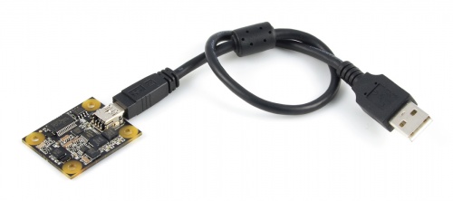
Next, you will need to connect the pieces:
- Connect the PhidgetSpatial to your computer using the USB cable.
Now that you have everything together, let's start using the 1056!
Using the 1056
Phidget Control Panel
In order to demonstrate the functionality of the 1056, the Phidget Control Panel running on a Windows machine will be used.
The Phidget Control Panel is available for use on both macOS and Windows machines.
Windows
To open the Phidget Control Panel on Windows, find the  icon in the taskbar. If it is not there, open up the start menu and search for Phidget Control Panel
macOS
To open the Phidget Control Panel on macOS, open Finder and navigate to the Phidget Control Panel in the Applications list. Double click on the icon to bring up the Phidget Control Panel.
For more information, take a look at the getting started guide for your operating system:
Linux users can follow the getting started with Linux guide and continue reading here for more information about the 1056.
First Look
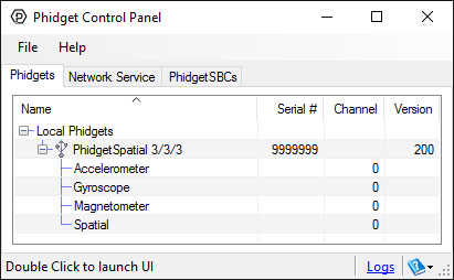
After plugging the 1056 into your computer and opening the Phidget Control Panel, you will see something like this:
The Phidget Control Panel will list all connected Phidgets and associated objects, as well as the following information:
- Serial number: allows you to differentiate between similar Phidgets.
- Channel: allows you to differentiate between similar objects on a Phidget.
- Version number: corresponds to the firmware version your Phidget is running. If your Phidget is listed in red, your firmware is out of date. Update the firmware by double-clicking the entry.
The Phidget Control Panel can also be used to test your device. Double-clicking on an object will open an example.
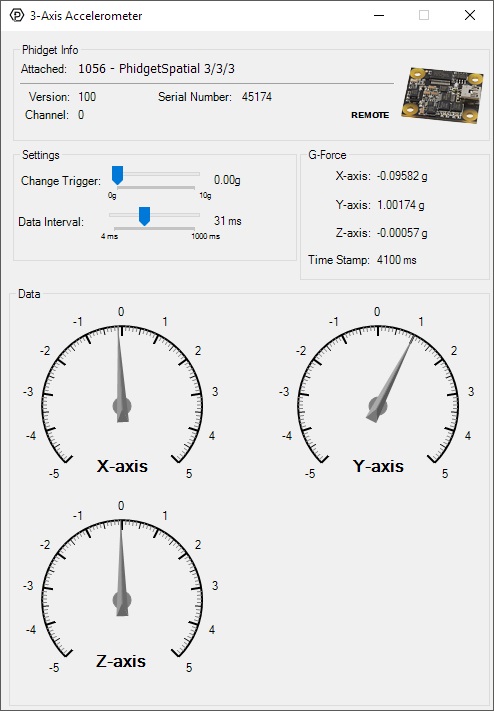
Accelerometer
Double-click on the Accelerometer object in order to run the example:
General information about the selected object will be displayed at the top of the window. You can also experiment with the following functionality:
- Modify the change trigger and/or data interval value by dragging the sliders. For more information on these settings, see the data interval/change trigger page.
- The measured values reported in g-force can be seen via labels as well as graphical dials. Try tilting the 1056 in different directions to see the labels and graphics change.
- An extremely accurate timestamp is also reported with the g-force values.
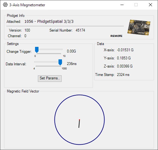
Magnetometer
Double-click on the Magnetometer object in order to run the example:
General information about the selected object will be displayed at the top of the window. You can also experiment with the following functionality:
- Modify the change trigger and/or data interval value by dragging the sliders. For more information on these settings, see the data interval/change trigger page.
- Use the Set Params... button to set the calibration parameters. For more information about calibration, see the technical section.
- The measured values reported in Gauss can be seen via labels as well as a graphical diagram. The diagram can help you visualize the magnetic field vector.
- An extremely accurate timestamp is also reported with the Gauss values.
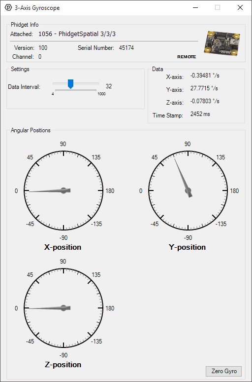
Gyroscope
Double-click on the Gyroscope object in order to run the example:
General information about the selected object will be displayed at the top of the window. You can also experiment with the following functionality:
- Modify the change trigger and/or data interval value by dragging the sliders. For more information on these settings, see the data interval/change trigger page.
- The Zero Gyro button is used to compensate for the drift that is inherent to all gyroscopes. The gyroscope primer has more information about this subject.
- The measured values reported in degrees per second can be seen via labels as well as graphical dials. Try rotating the 1056 in different directions to see the labels and graphics change.
- An extremely accurate timestamp is also reported with the g-force values.
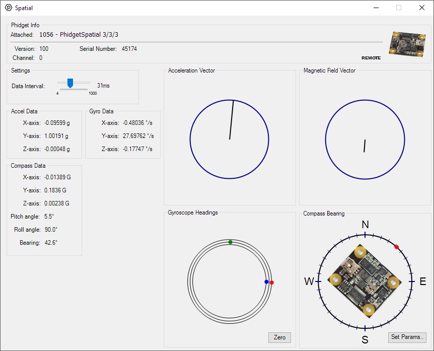
Spatial
Double-click on the Spatial object in order to run the example:
The Spatial example demonstrates that you can receive data from the accelerometer, gyroscope, and magnetometer all at once by using the Spatial object rather than the other three objects individually.
Finding The Addressing Information
Before you can access the device in your own code, and from our examples, you'll need to take note of the addressing parameters for your Phidget. These will indicate how the Phidget is physically connected to your application. For simplicity, these parameters can be found by clicking the button at the top of the Control Panel example for that Phidget.
In the Addressing Information window, the section above the line displays information you will need to connect to your Phidget from any application. In particular, note the Channel Class field as this will be the API you will need to use with your Phidget, and the type of example you should use to get started with it. The section below the line provides information about the network the Phidget is connected on if it is attached remotely. Keep track of these parameters moving forward, as you will need them once you start running our examples or your own code.
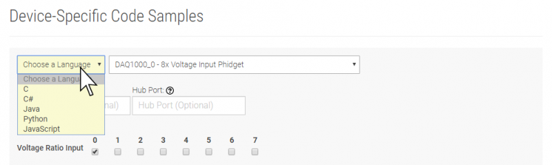
Using Your Own Program
You are now ready to start writing your own code for the device. The best way to do that is to start from our Code Samples.
Select your programming language of choice from the drop-down list to get an example for your device. You can use the options provided to further customize the example to best suit your needs.
Once you have your example, you will need to follow the instructions on the page for your programming language to get it running. To find these instructions, select your programming language from the Programming Languages page.
Technical Details
3-Axis Accelerometer
For more information on how to use the accelerometer, check the Accelerometer Guide.
3-Axis Gyroscope
For more information on the gyroscope, see the Gyroscope Guide.
3-Axis Magnetometer (Compass)
The magnetometer reports the sum of all magnetic fields acting on the 1056 device. The earth's magnetic field is only one source that affects this measurement. In order to get accurate bearing data from the magnetometer (i.e. to find magnetic north as a compass) any interfering magnetic effects need to be calibrated out. For more information about calibration, see the section below, or the Compass Guide.
Any magnetic field that is stationary with respect to the 1056 device, and less than ± 3 Gauss, can be calibrated out of the magnetic field measurement. This includes both hard and soft iron effects caused by nearby ferrous and magnetic materials. Interfering magnetic fields that vary in strength and orientation with respect to the 1056 device cannot be easily calibrated out.
Magnetic field data will become unavailable for ~28ms every 2 seconds as the compass perform internal calibrations. During this time, polling the magnetic field will return EPHIDGET_UNKNOWNVAL, or throw an UNKNOWNVAL exception. The magnetic field data in the SpatialData event will equal PUNK_DBL.
Magnetometer Calibration Guide
In order for your magnetometer to provide accurate heading information, it must be calibrated.
Follow this guide to complete the calibration process.
1. Open the Magnetometer example for your device, and click the Calibrate button. This will open the Compass Calibration tool.
2. If your device supports heating, we recommend checking the HeatingEnabled checkbox. Wait for the temperature reading to turn green:
If your Spatial does not support heating (neither of the above controls will be available), you can skip this step.
3. Next, decide if you're using 2-axis or 3-axis calibration:
● If the spatial is free to move in all directions, use 3-axis
● If the spatial is being kept mostly level (e.g. in a car), use 2-axis
4. You can leave the Local Field Strength at 1.0 for general use since magnitude doesn't affect heading. If you need more quantitative results, look up
your local value.
5. Make sure your Phidget Spatial is firmly in the position you intend to calibrate it for, and begin by clicking the Start button.
Begin rotating the structure your Phidget is mounted to. Notice the red dots appearing on the graph.
6. Try to rotate it so that it fills out as much of the sphere (or circle in 2-axis mode) as possible. When you're finished, click Stop.
You should now see red and green spheres (or circles) in the graph. The red one is the raw measurements, and the green one is the calibrated measurements.
Newly calibrated data from the magnetometer will be indicated by a green line that matches the sphere. The green sphere should be more centered than the red
one. If not, try repeating the calibration.
You're now done the calibration process! On most Phidget Spatials, the calibration will be stored in flash, so it stays calibrated to this environment even
across power cycles.
7. If you need to repeat this exact calibration, you can save the values listed in the text box.
You can use these values in the setMagnetometerCorrectionParameters method. See our
API Documentation for more details.
Further Reading
For more information on magnetometers (compasses), see the Compass Guide.
What to do Next
- Programming Languages - Find your preferred programming language here and learn how to write your own code with Phidgets!
- Phidget Programming Basics - Once you have set up Phidgets to work with your programming environment, we recommend you read our page on to learn the fundamentals of programming with Phidgets.